- 50 years on: updating the Triang Maunsell L1 Class loco. -

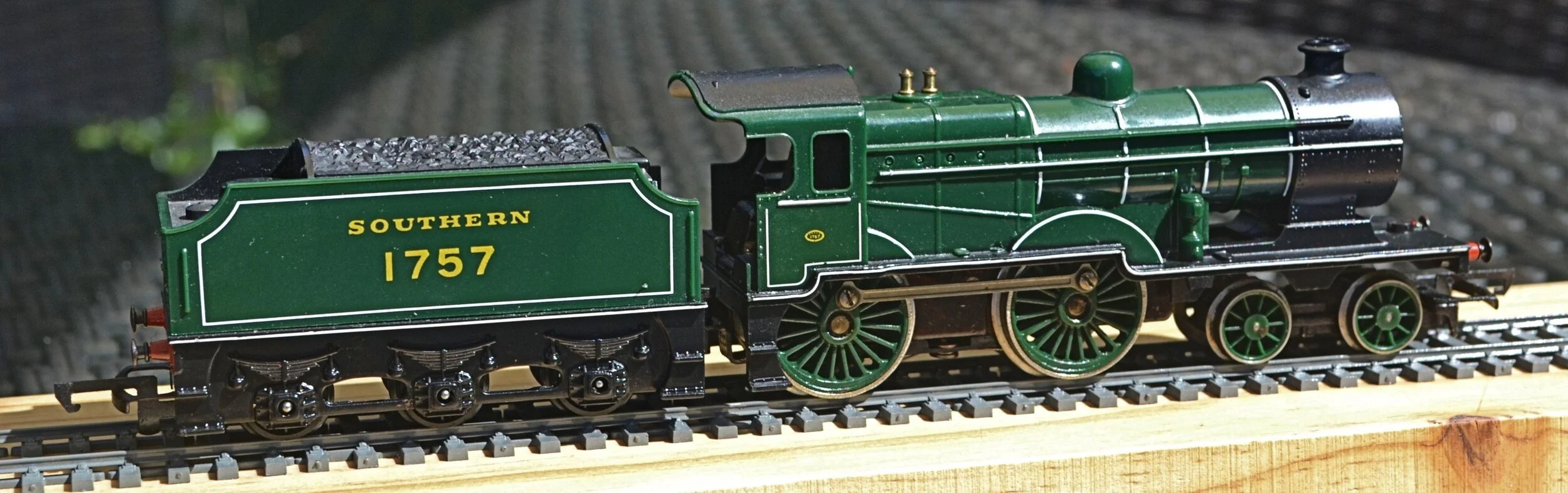
Richard Maunsell’s 4-4-0 Class L1 express loco
The origin of this photograph is unknown. No copyright infringement is intended.
The prototype
In the mid-1920s, Richard Maunsell [as CME of The Southern Railway] designed the 2-cylinder L1 Class essentially to both replace the Wainwright L Class locos and provide a more-powerful 4-4-0 for the London-Folkestone expresses. The L1 Class was built by The North British Locomotive Company and was introduced to service from 1926. Although progressivley replaced on various routes by the Schools, the King Arthurs and the Bulleid Pacifics, this class of 15 locomotives worked quite widely across the Southern [and BR(S)] until final withdrawl in 1962. Sadly, none has entered preservation.
The model
Triang introduced their model of the L1 in a BR livery in 1960. It was their first release of a Southern Railway locomotive and also their first model to feature open-spoked wheels: it was, thus, something of a game-changer at the time. Whilst not completely accurate in terms of dimensions, the Triang model captures the stylish, uncluttered and pleasing outline of Maunsell’s design well and it remains the only r-t-r model of this class to have been manufactured.
The model that I have used for this project, the Southern gloss green version, was Triang's last throw of the dice for this engine and was available in '71-'72 only.
![As you can see, a near mint loco with easily rectified damage to the step [other side]. The planned livery will be all-over black with Bulleid’s early-'40s 'Sunshine' lettering.](https://images.squarespace-cdn.com/content/v1/541ebef9e4b0e2c159721915/1590926247833-QE2C6D1XXZMKZHW1V33T/DSC_0049.JPG)
As you can see, a near mint loco with easily rectified damage to the step [other side]. The planned livery will be all-over black with Bulleid’s early-'40s 'Sunshine' lettering.
Before commencing, my initial problem lay in acquiring my donor model. The three usual eBay dealers weren't worth considering: one could sell me a model for £189, and another for £159 and the third, a tender for £45. There were a few between £50 and £80, but as invasive surgery was going to be a necessary option, I was neither keen to cut up a good example nor spend a lot on something which might not succeed anyway. In the end, I bought a ‘spares or repair’ L1 for £24.99 post free as a buy-it-now. It didn’t run and had a broken step and some damage to the footplate: none were problems though as I had a couple of low-mileage XO4s which I could drop in and the broken step came with it.
I also acquired a Bachmann N Class tender to accompany the loco [the Triang tender being incorrect and rather more LMS in outline].
The surgery
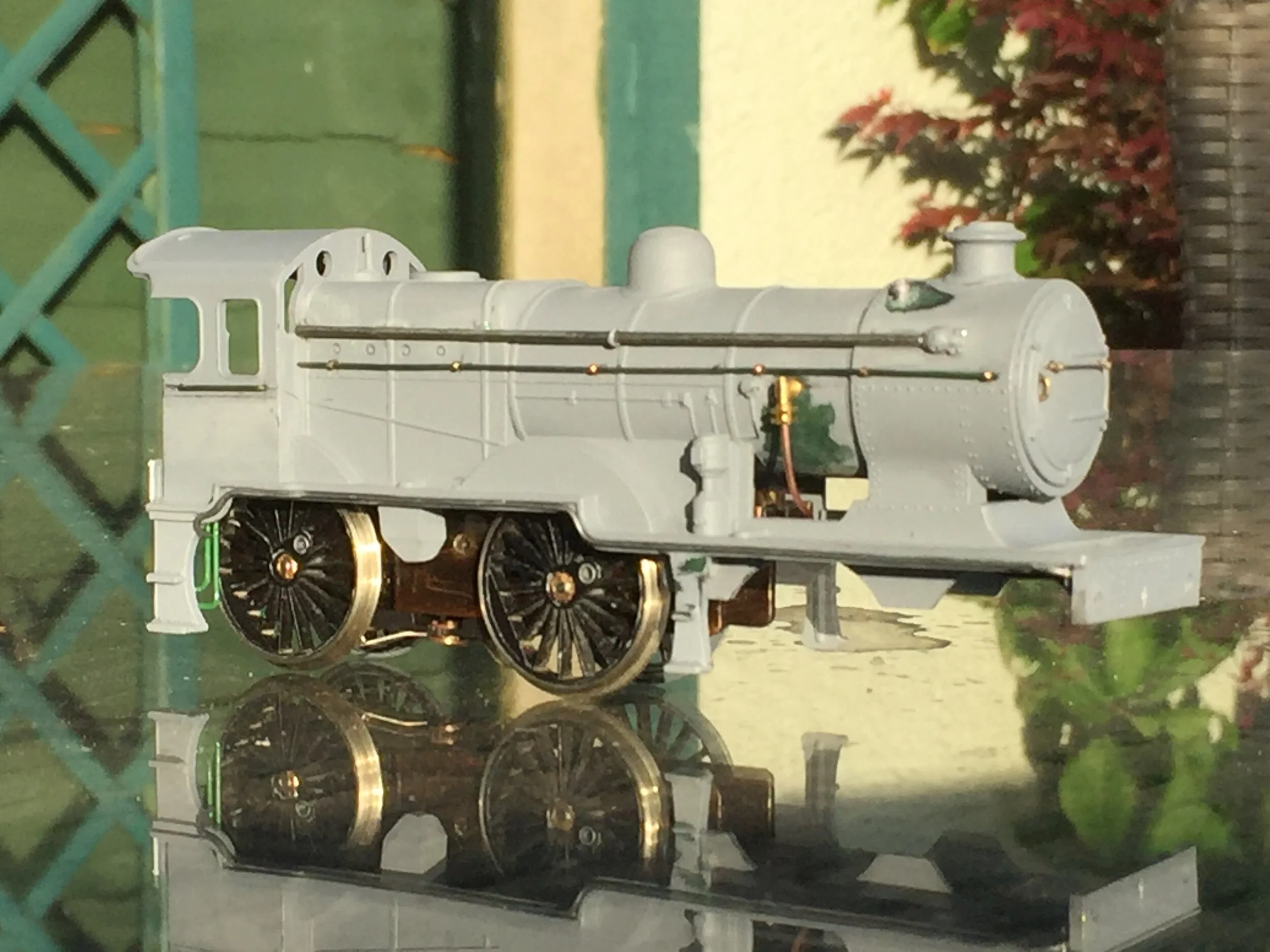
Work on the body has commenced. The damage to the rear of the footplate has been remedied, all of the handrails - and what maybe the long ejector pipe on the right hand side - have been removed, the broken step replaced and the buffer beam sawn off and replaced by a more-detailed white metal one.

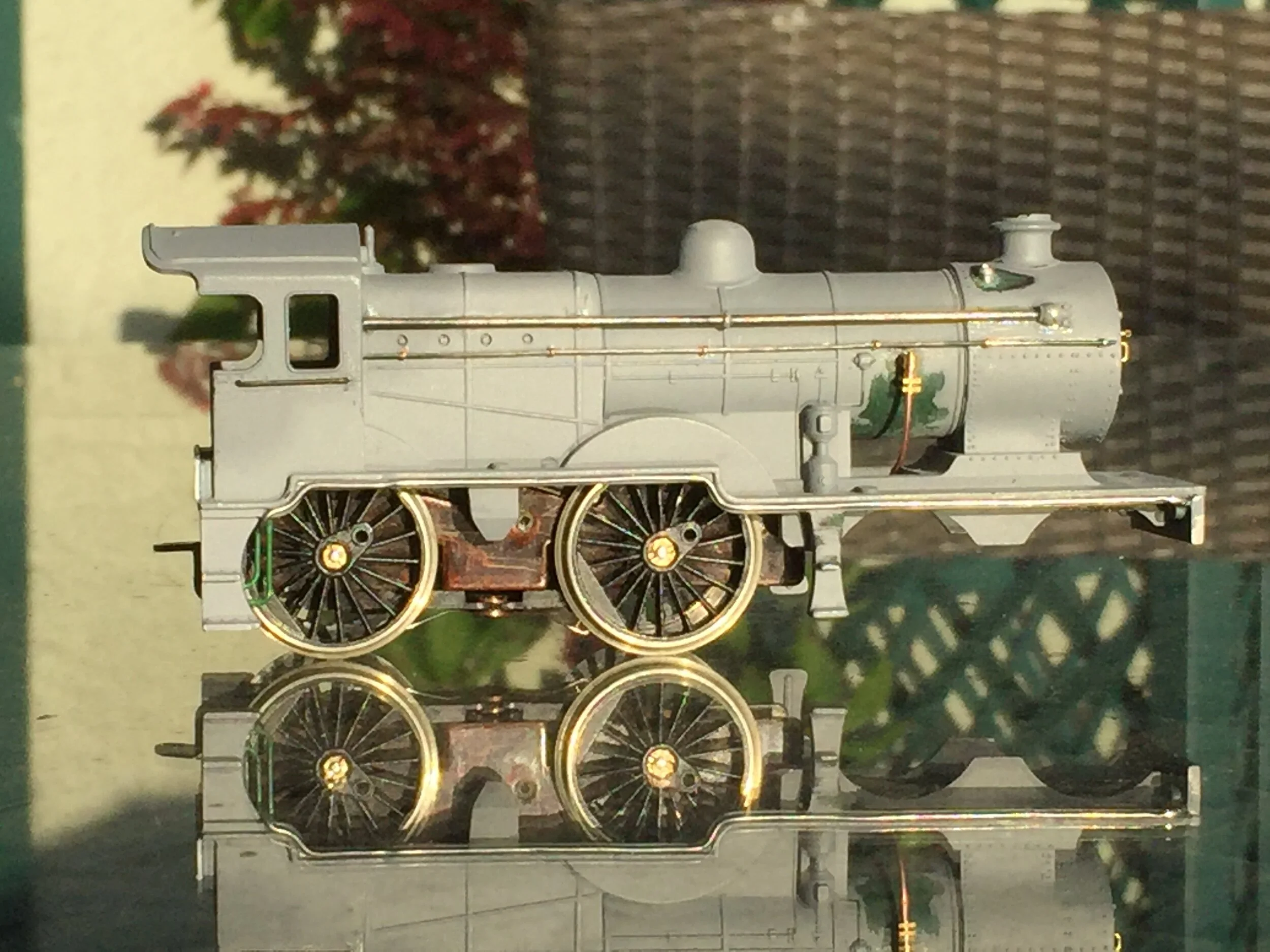
Removing the long runs of railing and pipe work was time-consuming but not difficult [the photo earlier, above, show the amount of plastic to be removed]. A sharp scalpel and some wet-and-dry saw to that [with no body damage to speak of]. The Triang buffer beam was removed because it was hopelessly undernourished and far too shallow. Fitting a replacement [not 100% accurate, but good enough] will also result in the new buffers sitting at the correct height, so eliminating the traditional Triang problem. The body is shown above in primer to highlight any areas which require further attention [mould lines in particular].
It is likely now that I will use the original Triang chassis but fitting a new five-pole motor and 26mm. Romford wheels. Had the club been open and I had access to the workshop, I could have adapted the massive Triang chassis block to take a different motor and gearbox, but I have no vice at home and I have also run out of sufficiently beefy hack-saw blades to attack the mazac casting.

Two of the really prominent features of the LI's body are the various external plumbings. I fitted have now fitted some of those: the short pipe entering the smoke box is made from solder [second photo], a really useful material for pipe-runs, being so malleable. I had no idea what that pipe was for but RMWeb advises that it is the feed to the exhaust steam injector. The long pipe run along the other side is the ejector pipe and I made that out of an adapted white metal GWR ejector pipe. Like the buffer beam, it is not 100% accurate as the bore is a little large [and it is also a fraction short] but it looks like what one would expect to be there. It is fitted to the boiler half-way along with a split-pin [which, from three feet, actually looks quite realistic!].

The small hole in the running plate below the smoke box door is there to take a screw to attach the front of the chassis to the body. You can see from the photo at the beginning of this topic that the screw is unattractively prominent. I had hoped to eliminate this but the chassis adaptations referred to below mean that it has to stay - there being no other easy method of securing the chassis at that location. I have found a much smaller and less visible screw however and when countersunk, painted black and hidden by a route disk, it shouldn't be too visible.
A few more bodywork jobs will follow, including drilling out holes for all of the handrails, reinstating some rivet runs with resin rivet decals, cutting out perspex side windows and fabrication some of the under-footplate pipe work.
The chassis also had some attention. In spite of what I said earlier, swapping the wheels was a game-changer in every sense. Once the original Triang wheels had been removed, there was no going back: refitting them was simply not possible and one had to hope that the Romfords would fit. Happily, they did, although the axle holes required a little reaming to accept the bushes [which themselves required a little reaming out as well]. The wheels spin very freely. At this point I realised that I could not fit the replacement XO4 motor that I had lined up because I had no suitable replacement for the original Triang plastic gear cog. I wasn't able to pull the worm off the XO4 either, to fit a larger one, and so a complete re-motoring/re-gearing was the only option. This took a long time but everything fits at last. A great deal of metal work was cut away from the Triang chassis with a junior hacksaw [and my only blade] so that I could install an Anchoridge five-pole DS10 motor with its integral gearbox. Luckily, I had just one gear cog that would engage with the worm and it spins nicely. I'll put some electricity through it soon, but I'm not anticipating any problems.

A couple of further little jobs now done: Clack [boiler side] and Snifting [smoke box top] valves removed from each side, together with associated pipework [arduous], injector pipes and overflow installed under footplate and the long run of pipework for the vacuum pipe attached under the length of the right-hand running plate [made of 1mm solder]. The last item will barely be visible when the body has been painted black, so I might pick it out very lightly in a sort of blackish rusty silver.

That injector pipe running the length of the boiler is also beginning to annoy me. See my later comments…..
As well as the distinctive pipework, one of the other highly visible features of the L1 are the large sandboxes. These are not modelled on the Triang model although, oddly, their covers do appear on the running plate - you can see them in the photo, above. The forward cover is not quite in the right place however and so will not match up with its sandbox, which has to be placed closer to the rear of the [now repaired] step. I filed these up out of pieces of white metal and plastic card. They look a little irregular frankly, but are better for primer. When painted black and placed under the running plate they should look alright
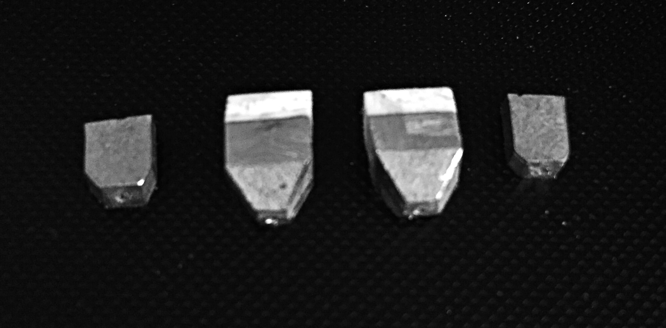
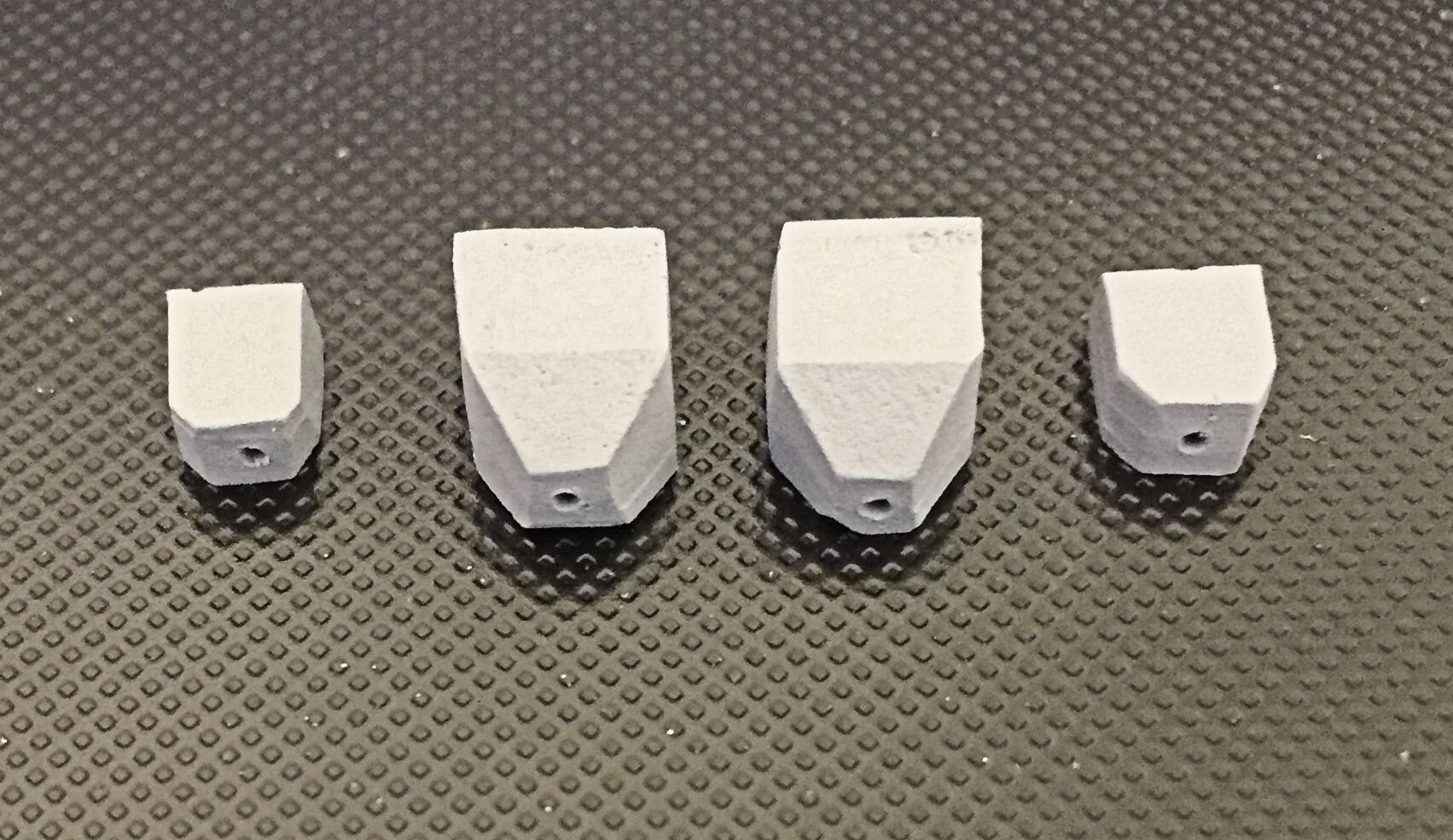
As hinted at earlier, I have removed the long white-metal ejector pipe I fitted the other day as it really was too over-scale and was beginning to annoy me. I have replaced it with a finer steel rod and am more comfortable with it now. The sand boxes have been fitted but attaching their discharge pipes will be the very last part of the build. All of the separate handrails have been fitted, as has a small smoke-box door handle. The replacement brass and copper clack valve assembly is a push fit at this stage, for photographic purposes only. The replacement snifting valves were not of the correct pattern and so have not been used. In their place I filed up and fitted some white-metal ones [contrapted from an LNER safety-valve casting!]. they’ll do…
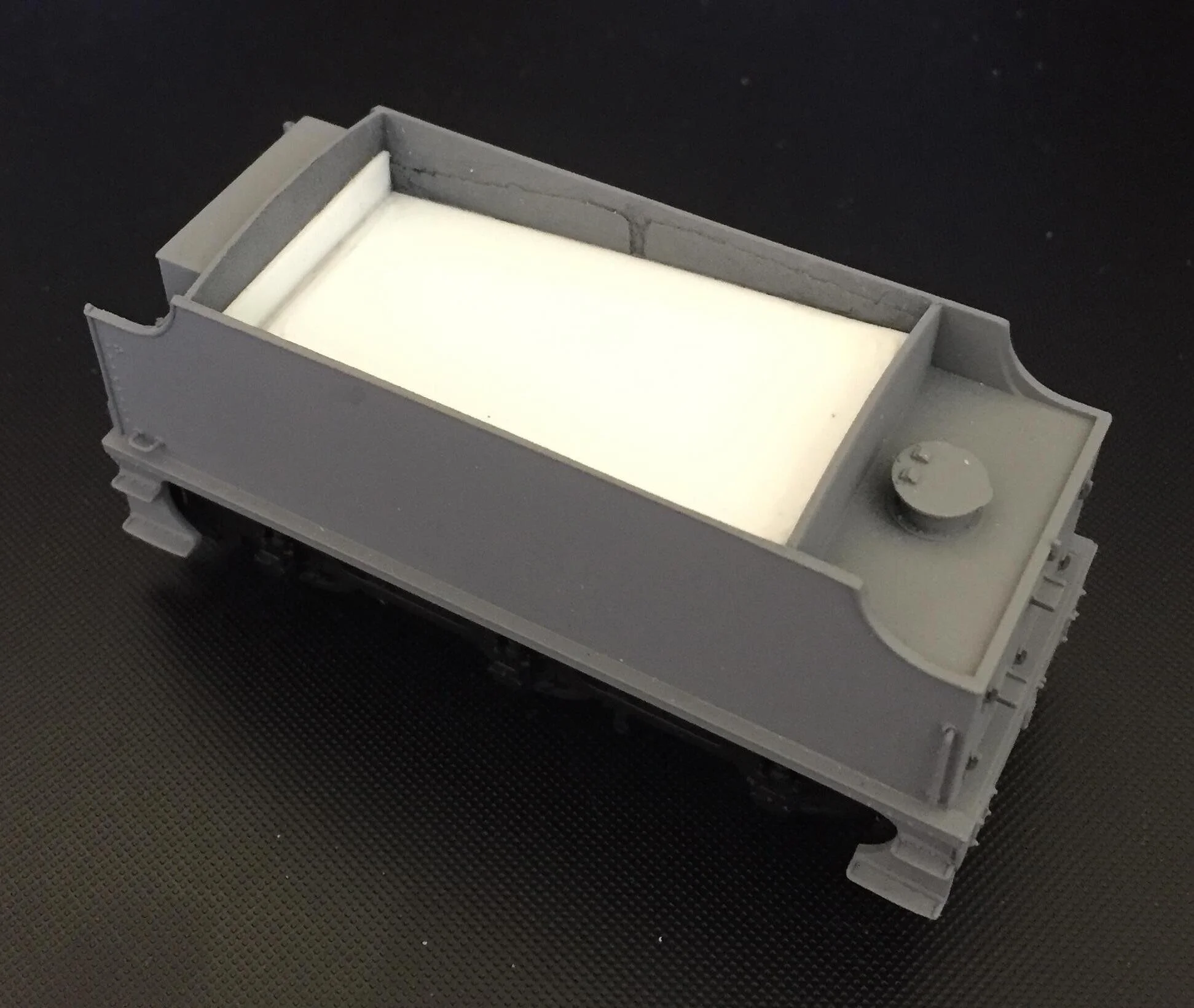
A start has also been made on the Bachmann N Class straight-sided tender. This was difficult to source and eBay prices were outrageous with one ‘dealer’ wanting £45 for one. This one was acquired for £12 post-free. It came with very minor and easily-rectified damage.
Some small repairs to the tender chassis will be required in due course but, in the meantime, the dummy coal load was cut out with a fret saw and a plastic card box made up to hold the replacement real coal load.
The body has received a coat of primer to check for any irregularities.

Returning to the loco body, SR pattern lamp irons / route indicator holders have now been fitted. These are brass etches, bought on-line. I normally make my own from brass strip but I thought some 'proper' ones would be nice here. I'm a little disappointed by their size however, definitely over-scale and a little coarse. The smoke box side irons required a lot of filing to fit in the correct position, too. After a flash of primer and then the top coat, they do not now look too bad. I have also reinstated the cab-side rivets and added vertical handrails to the cab, as the progress photo, below, shows.

The body, after priming, sprayed with Halfords’ Matt Black.

The loco body has been set aside for the moment and attention has been given to the tender.
The chassis required some repair as the lower parts of some of the brake hangers were missing and, consequently, it was not possible to fit the rigging. The missing parts were fabricated from 1mm square plastic strip, laminated for strength and then drilled. The dummy coal load was removed a while back but a plastic card box has been fitted to hold real coal in due course. A brake stanchion was also missing and a white metal replacement has been fitted.

And now, sprayed black, numbered and lettered, and with the buffer-beam painted and sprung buffers fitted. The Pressfix decals are given a coat of Klear once they have been applied and then, when dry, the side is sprayed with a satin varnish to seal it against handling
Coal, couplings and a vacuum pipe await fitting. A loco / tender coupling also awaits fabrication. Otherwise, the tender-part of the project is complete.

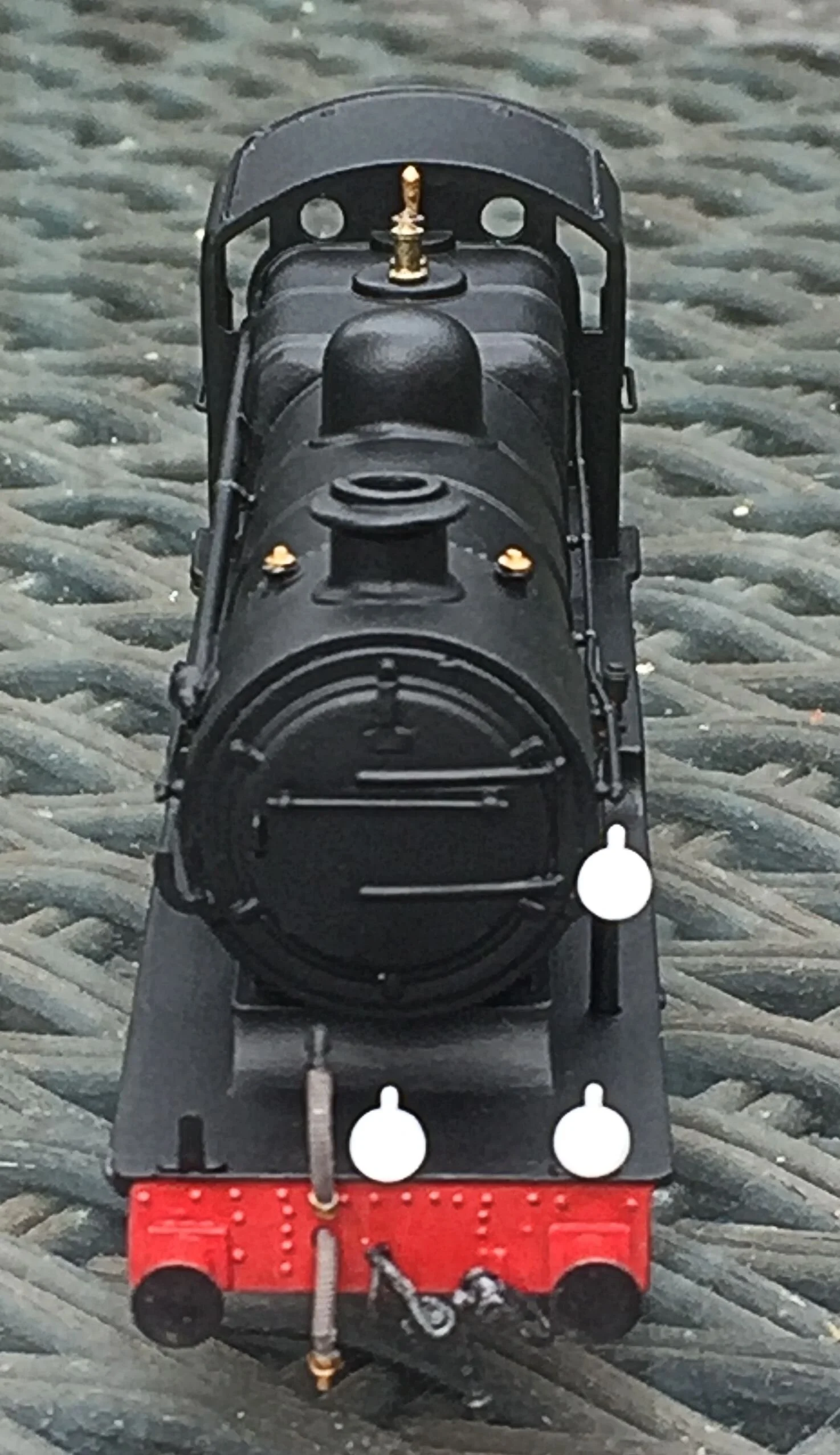
Returning to the loco body, most of the external detail has been fitted and the side-sheet windows have been glazed with perspex cut to size and fixed in place with Klear. The forward-facing windows and spectacles will be glazed with Glue-and-Glaze in due course. The indicator disks will also be toned down slightly and the brass and copper work of the clack valves will receive a very light brass and copper wash too, to suggest that the black overpaint is wearing off in use.
The dummy coupling on the front buffer-beam is not twisted, but is hanging on the small hook fitted to keep it clear of the track when in use. I really should have numbered the buffer-beam before attaching the hook however:’retro-numbering’ is now going to be quite difficult [but still necessary].
The route indicator disks suggest in this case a service from south London to Brighton.

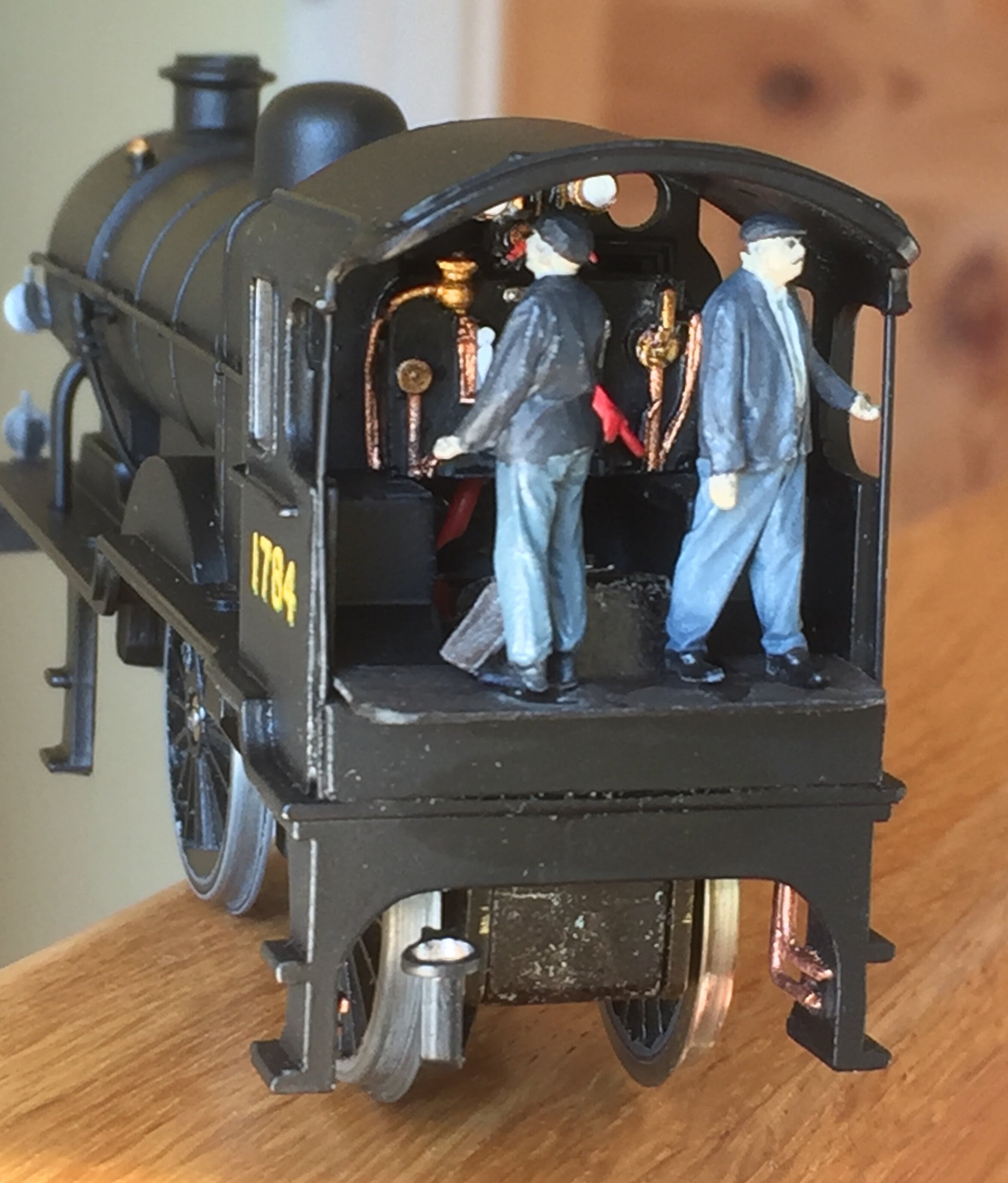
This is not a particularly good image but it shows the backhead now fitted.
Because the upper-half of the cab is so open and visible, and behind the backhead is a much bigger hole in the body moulding to make space for the original XO4 motor, cosmetically something was needed. I used an anonymous white-metal casting from the bits-box and it is probably quite incorrect for this class of locomotive! That said, I have never seen a photograph of the inside of a L1 cab, so who’s to know anyway?
Fitting a backhead was necessary though, and it’ll do. It has had to be cut in half to provide clearance for the chassis and motor. Once the crew and fall-plate are fitted however, this will not be so noticeable.
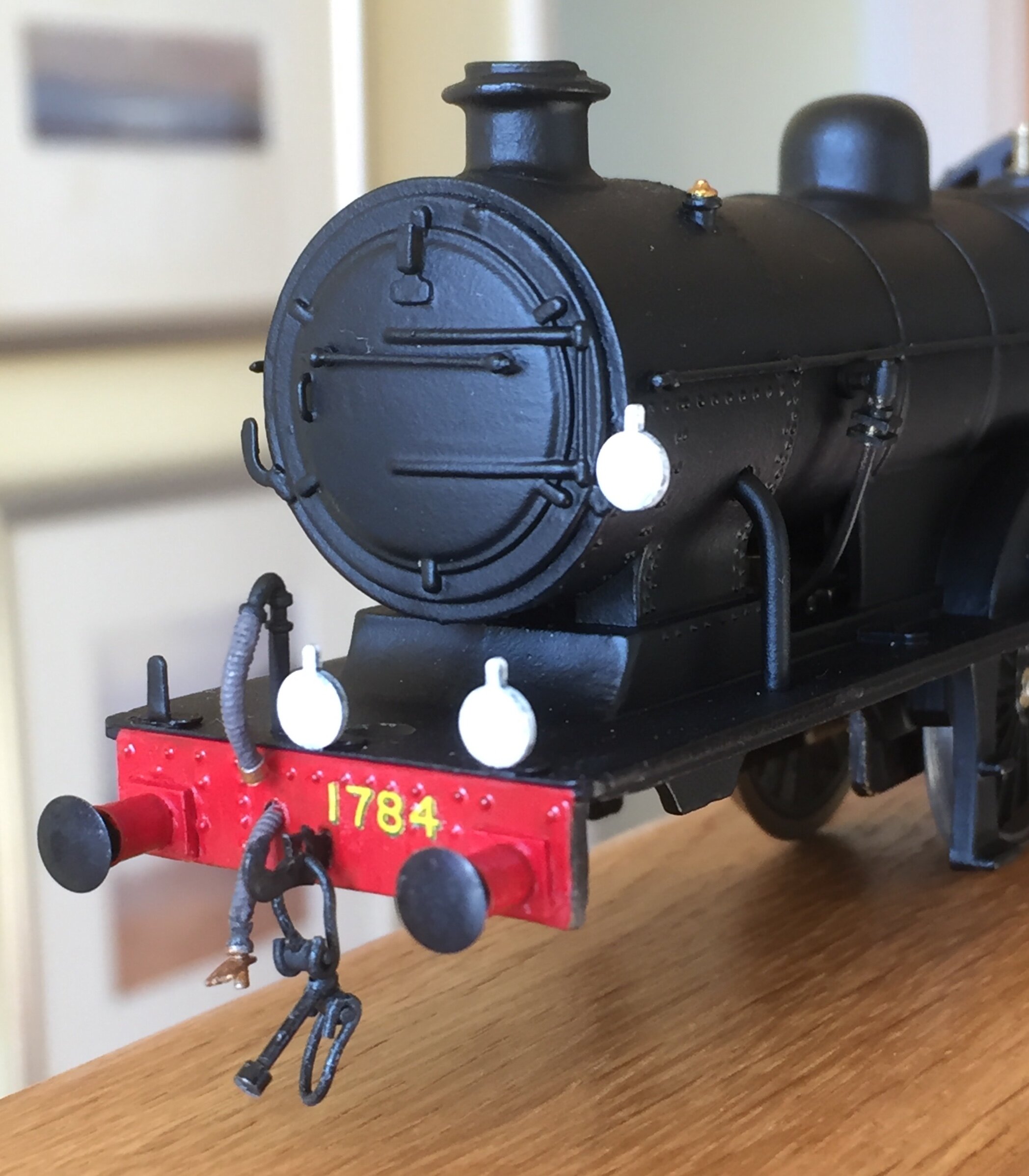
The tender has been coaled and is now complete and I have found some acceptable plastic brake assemblies for the chassis - luckily they fit nicely against the drivers [more-or-less]. The front buffer beam has been numbered [at last] and came out acceptably. I was concerned that the small hook for holding up the coupling and the over-scale rivets might get in the way , but not so. I think that the number should be a little more to the right, but that wasn't possible.
Now, what definitely hasn't worked has been the fitting of the crew. The two that I bought did not fit as their postures were wrong [my fault]. They have since been put into Talgarth Hall and are a great improvement there. The the two from the Hall were then placed onto the L1 fall plate but look absolutely awful: they are just too stiff but the real problem lies in the cab floor rather than the figures. Because the chassis extends far back into the cab, standing crew can only be placed on the extremity of the fall plate that I made. The cab floor is also a good scale 2ft too high [again, a chassis issue], which means that the crew have to stand unrealistically together in the middle and far too close to the roof. It just doesn't work. I have since removed them and the loco will run sans crew. This work now completes the body and only some chassis issues remain [most cosmetic].
This enjoyable build is very nearly finished now, with just some cosmetic issues to address and pipes to be formed and added to the sandboxes.
Nothing ever runs to plan however and, at the 11th. hour, a number of gremlins crept into play. First, an electrical fault preventing the loco from running. Power to the terminals and the motor ran: power to the wheels and it didn't. So an hour or two fiddling around with the pickups and the fall plate got that sorted. Then I found that my patiently constructed sandboxes fouled the con rods and the chassis could not be fitted to the body. Having never fitted the con rods in 'dry run' mode, that came as a surprise. New sandboxes were constructed out of laminates of plastic card and glued in place. All good now. Brake hangers have also been glued to the sides of the chassis and improve that rather exposed, empty area considerably. I couldn’t use the white-metal ones that I had set aside because of a risk of shorting: I used some plastic ones instead.

There is a fall-plate in the above photo, but it is difficult to see.
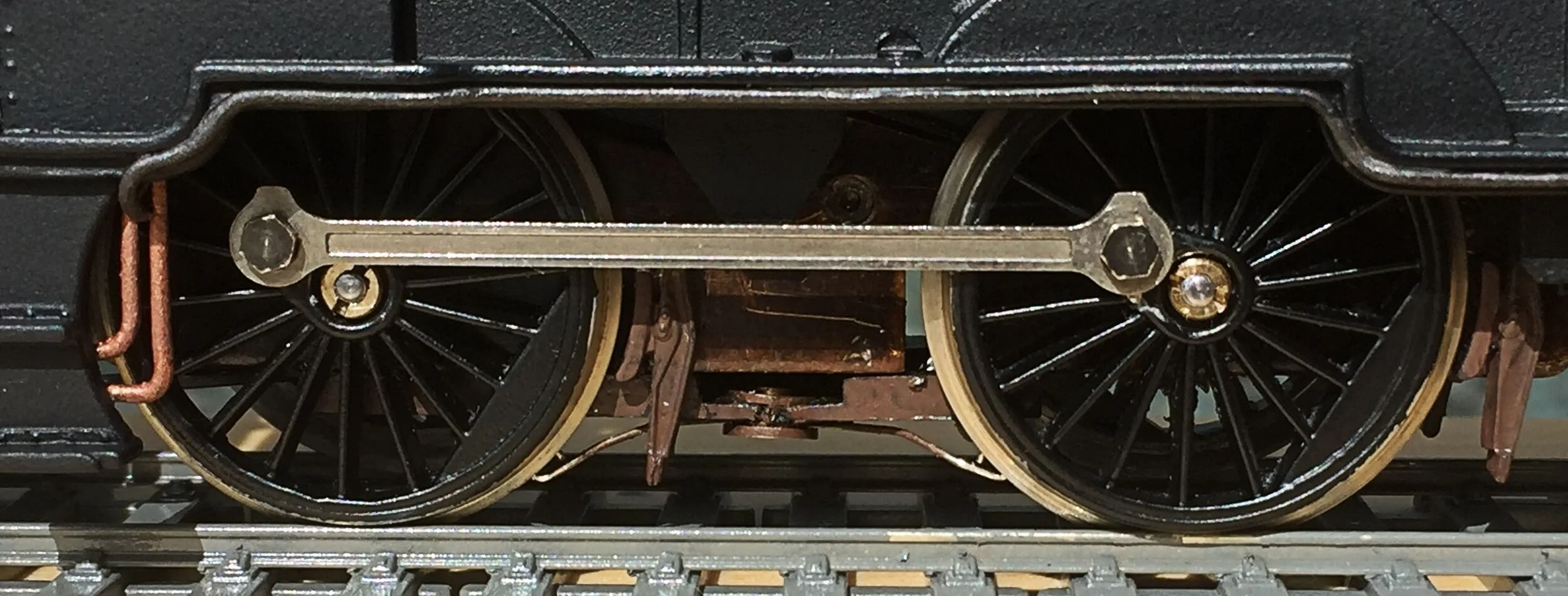
The front bogie has had late attention with 3mm cut off the front to remove the hideous Triang guard rails and the obtrusive mountings for the Triang coupling. White-metal guard rails have been fitted in place and finer profile wheels substituted for the original cheese-cutters. The drivers have been painted and fitted and are driven by the original Triang rods, but those are secured with much neater, and smaller, bolts. Overall, I'm really happy with the way that this conversion is proceeding.
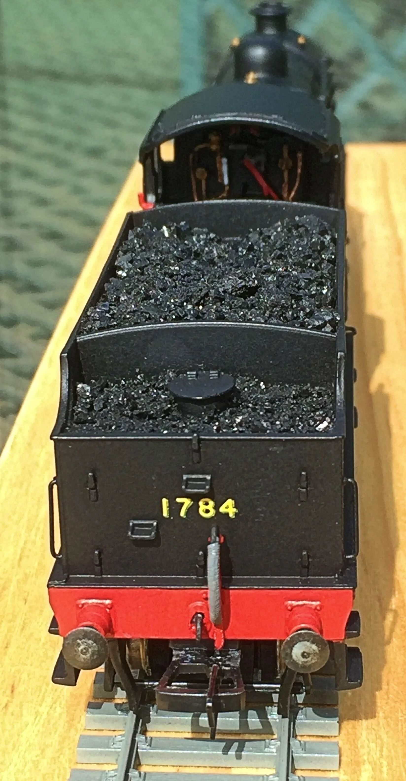
I'm still in two minds about crew however. I have found some smaller white-metal [or maybe pewter] chaps and may well paint them up for service. The tender has also received the final details it required, together with [real] coal. I have tried to model the coal showing it with a dip at the front where it's beginning to drop forward from use. The dropped coal around the water-filler would not endear the trimmers to the Shed Master.
Two bits of detail I remain uncertain about: fire-irons and running lamps for use at night. For the latter, I have SR-pattern lamps but do not know where on the loco they would have been stored when not in use. Also, I am equally uncertain about the stowage of fire-irons: were they simply thrown over the coal as they were on many GWR tenders?

The next photos will see the conclusion of this interesting build. They’ll follow soon…..
Conclusion
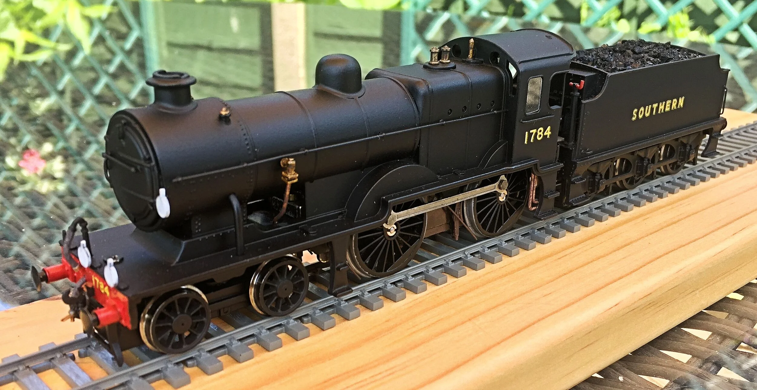
The copper and brass-work has been toned down and dirtied and sand-pipes fitted and painted. Apart from needing to paint in matt black the small fixing screw under the smokebox door, and dealing with a small paint scatch on one of the drivers, this conversion is now complete. A bittersweet moment really and it was an enjoyable project, something which I had been wanting to undertake for years. The next build will be by light years a more complex and trying affair, a Hawksworth Dynamometer Car, but you’ll have to wait for the blog elsewhere on my workbench to see it……..


Update
Since the above was written, the L1 has returned to the shed for repairs. The original motor and gearbox combination proved unsatisfactory after running-in and was removed. After further significant surgery to the chassis to enable the replacement motor to fit, a Portescap RG4 unit was inserted and additional pick-ups attached to the non-insulated wheels also. All is now well…