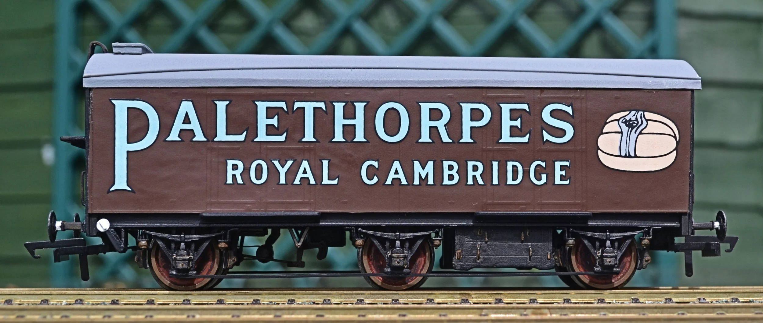
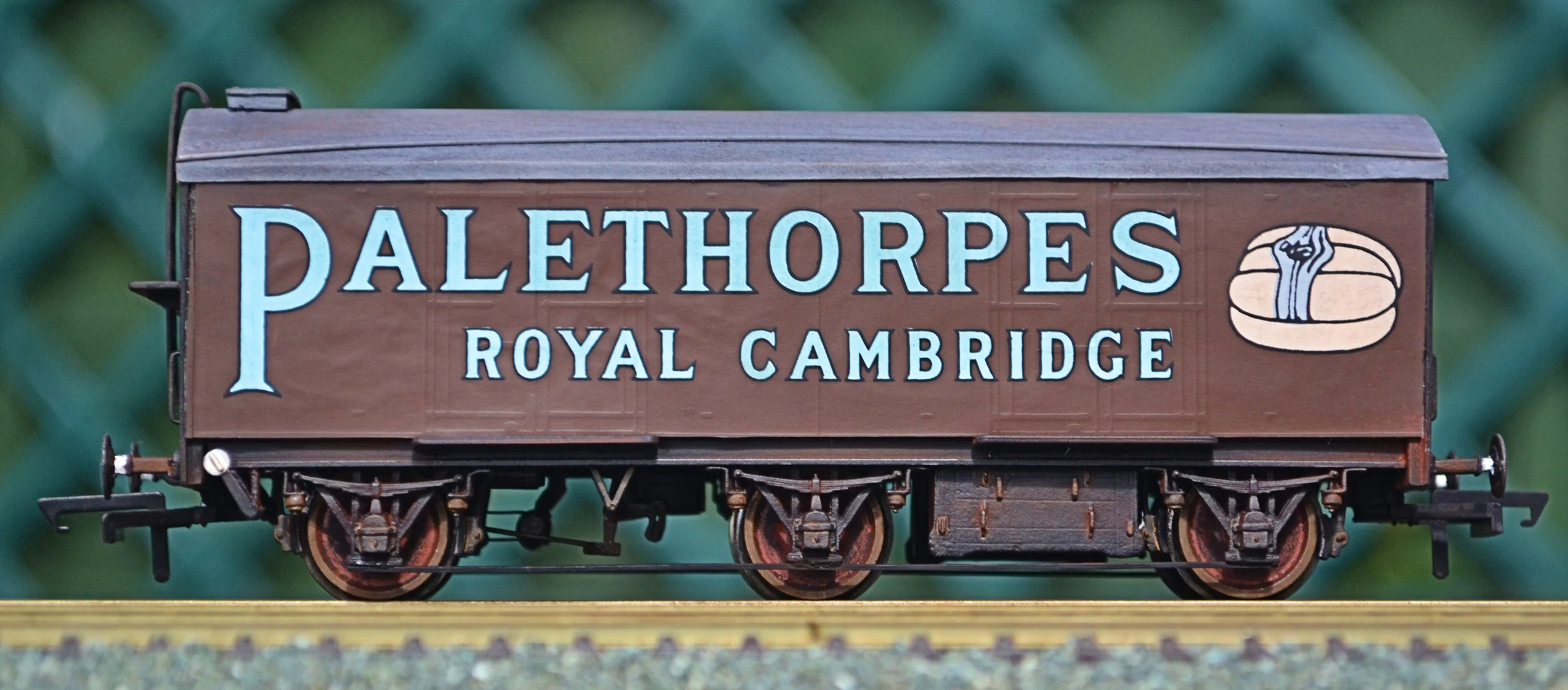
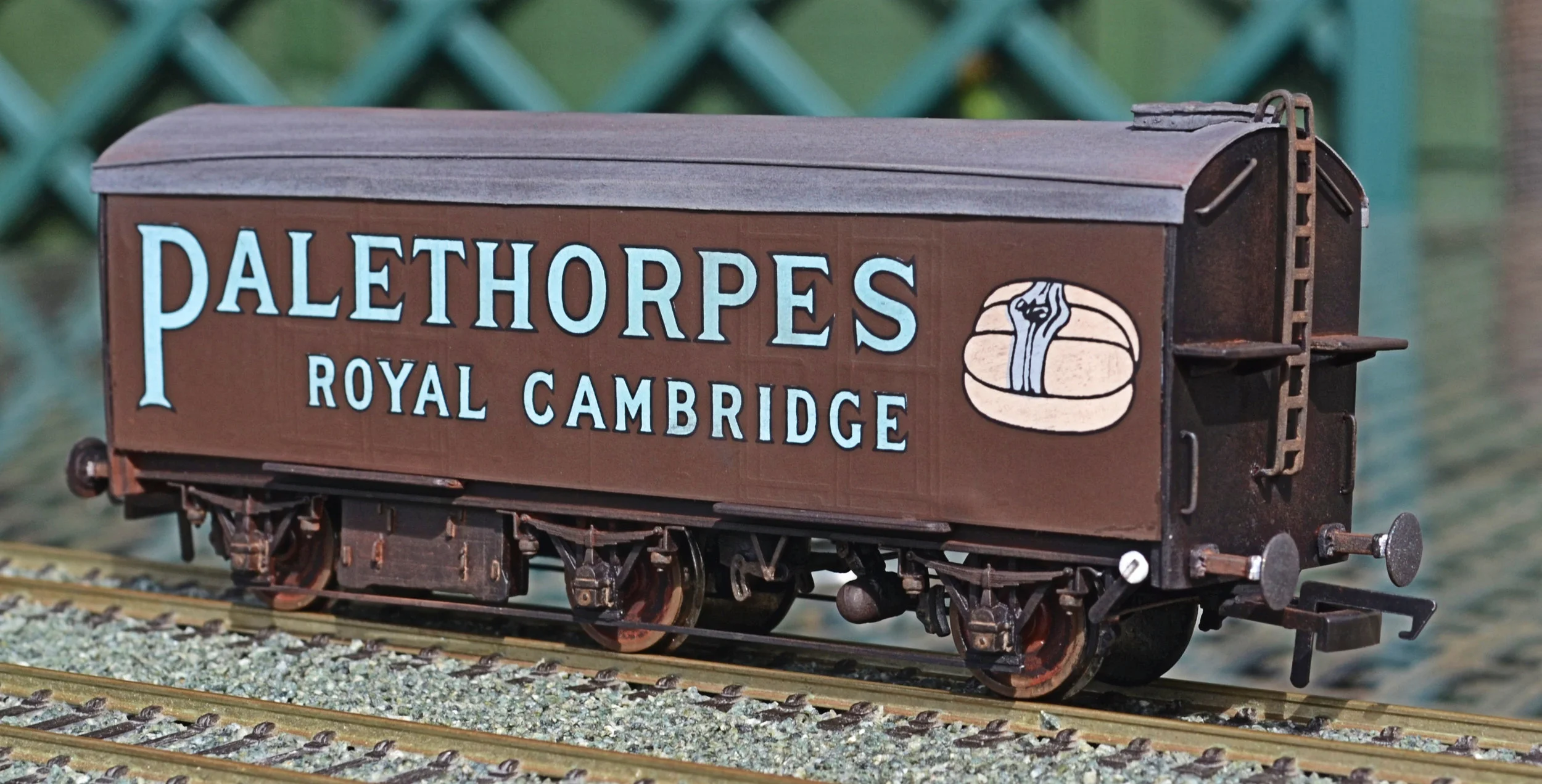
These attractive vehicles were built as a pair for Messrs Palethorpes of Dudley in 1936 and ran well into BR days. Numbered 2801 and 2802, they were often seen in the Cardiff area and so would not be out of place on any south Wales railway. An attractive r-t-r version is also available from Hornby. It has a number of flaws however, the underframe being particularly rudimentary and the overall dimensions somewhat compromised to fit the metal chassis frame.
The kit for this build of a Palethorpes 6-wheel sausage van was made in the early 1970s by W&T Manufacturing [Birmingham] Ltd. Comprising white-metal castings, plastic card, wood, some brass and an acetate body shell, it also has screen-printed plastic-film sides to attach. Assembling this kit is very much a return to old-fashioned modelling: screws and nails and a pin-hammer, alongside super-glue. I think the sides will require impact-adhesive however, to ensure as flat a fit as possible. Whether it will in fact even be possible to produce an acceptable end-product remains to be seen, but nothing ventured....
On opening the box and inspecting the contents, it quickly became apparent that the kit will present some real problems in construction. I noted also that the buffers were missing. Not a problem in itself, but a shame. The white-metal castings were generally quite good but the acetate 'tunnel' which is the body shell will be tricky. It is overlength by around 3mm and is very flexible/flimsy [but not flexible enough to lie flat to scribe and cut]. Further, it will be difficult to attach it to the white-metal ends as instructed because there is little surface to glue it to [a shallow rebate on each cast end]. Consequently, it's already obvious that it cannot be easily made in the way that the rather poor instructions suggest. I've found a way around that though - see later. The roof is a plastic card overlay. It first needs to be cut to size and then formed into a curve. I have no idea how to attach it to the acetate yet: impact adhesive? Maybe. Not a preference however.
The floor component is pine - or some similar softwood - and those white-metal castings which require fixing to it do not have holes large enough for small screws, hence a need for panel-pins or similar to enable attachment. I have dismantled old kits before which were assembled in this way, to scavenge spares.
However, the floor as supplied is over is terms of both length and width and also has a very slight warp. It is thus unusable. I'll substitute either 3mm ply or failing that, 3mm plastic sheet. I'd particularly like to use ply though, to be true to the original.
Wood it is and, binning the original floor, I cut a replacement out of 3mm ply: I was pleased to still be able to use wood and, so, keep faith with the original spirit of the model. I have had to use plastic strip for solebars however, a disappointment, particularly as it had to be super-glued to the floor. Once painted though it'll look the part.
The first two photos show the underside of the floor with the first set of W-irons being fitted. I've used 3x1mm brass nails with the domed heads filled down [some more filing needed though]. Both W-irons are fitted loosely at present in order that the correct spacing for the wheels can be determined. The screwed casting in the centre is for the middle axle. I've cut off the pin-points and it'll float freely to negotiate curves and points. At least, that's the intention.....
The next photo shows the acetate body shell. Cutting it to length was really tricky and it's somewhat bendy, too. According to the instructions, it should be fitted to the ends before anything else is done to the assembly. I'm going to leave it until the chassis is complete, with the ends added, before attaching it however. I'll also glue some L-section mouldings along the upper surface of the floor to give the shell something additional to adhere too: the rebates in the end castings simply do not have sufficient surface area for a strong 'stick'. Doing it this way will provide a strong, robust frame for the shell to drop onto, something it would not have had had I followed the instructions. I'm also using Gorilla Glue for this for the first time.
I've yet to determine how to attach the roof and in fact what material to use. Brass sheet would be best but I always find it tricky to cut. It also has very sharp edges. I'll start with plastic card [as supplied]. Shellacked card might be a suitable alternative, and would certainly be in keeping with the 50+ years age of the kit.

As mentioned earlier, the sides are litho-printed, quite floppy, soft plastic sheets. They are very slightly embossed which is correct; the surface detail on the original wagons was nearly flush [which makes the latest Hornby offering over detailed].
Again, I'll have to ignore the instructions with regard to attaching them. As described, their attachment would be the penultimate job. I can only see impact adhesive as being the effective glue for this job though, and as that requires a degree of pressing and smoothing, that handling would be impossible if the instructions were followed. There would be a near-certainty that the body shell would become detached from the ends. So, I'll attach them to the body shell before it is fitted as it will allow handling and supporting. The sides will also need GWR branding and a running number to be applied [Pressfix to the rescue here].

Next, another shot of the underframe, this time with the W irons and battery boxes loosely fitted. I've been quite impressed by the quality of the underframe castings and an accurate chassis is possible for this kit. There's a lot more metal-work to add though....

Now, in spite of the generally good quality of the white-metal castings, a close inspection of the brake mechanism components made me decide not to use them and substitute some etched brass and better castings in their place. I have retained but modified slightly the vacuum cylinder.
It’s not even clear from the ‘instructions’ how the original brake parts were to be assembled. The drawing in the photograph is the most detailed part of the instruction and was intended as a template to be cut out and stuck to the underside of the wooden floor. This is problematic however as a number of parts need to be glued to the floor. I don’t like glueing to paper, as suggested, as it risks becoming detached later. Consequently, I used it simply as a rough guide for component placement. You can see also the parts which I decided not to use.

The following photo shows the new brake gear in place, together with the dynamo, regulator box and various other parts. The centre W-irons have been fitted as they are cosmetic only, the axle being held by the centre casting. The rest of the W-irons have been fitted down one side only so that I can test wheel fit before attaching the others. A spray of primer will follow in due course, and then matt black. Incidentally, the floor is not warped, it's simply the way in which it is sitting.


I've been staring at the chassis for a while and have realised that the brake gear, as fitted, may be incorrect for this wagon: I have not been able to find a photograph which is clear enough to tell. No matter, it looks reasonably similar to that in the photograph at the head of this article and, when painted, will just look fine.
I have also to fit some thin wire pull-rods for the brake-gear and, in due course, truss rods under the W-irons and footsteps in various places.

Since the above photographs were taken I have removed and replaced the white-metal V-hangers from the end of the chassis: they were just too flimsy to withstand handling and one eventually broke. They have been replaced by a pair taken from an old Ratio plastic kit and handles have been added, too. Shown here in primer, they are more to scale and far more robust also.
The visible kink in the transverse rod has also since been rectified by replacing it with finer brass wire.
The chassis is now almost complete. The remaining W-irons/axle-boxes have been nailed in place and the wheels run in brass bearings. A thin brass strip simulates the dynamo belt and a brake pull runs from the centre unit to an end axle. This will be replaced though and re-routed under the axle with a bend to take it onto the hand-brake mechanism at the end of the chassis. Left to attach are tie bars, end steps and brake hangers. The following photograph show the chassis so far, painted black with the wheels weathered. The whole unit is extremely free-running.


Some more work has been done on the chassis, adding the brake hangers, the tie bars and re-routing the brake pull, and it is now complete.
The brake hangers were cut from their original one-piece mouldings and then attached, well packed-out, so that the blocks were in line with the wheel treads. Cosmetically they look far better when fitted this way. Note too that, prototypically, only the outer axles are braked.


The end castings were cleaned up and drilled for handrails [fine brass wire] and coupling hooks [white-metal] which were then glued into place. The end closest to the ice chest had its platforms glued into place as well. The positions for the handrails had to be gauged from some rather poor photographs and so they may not be 100% accurate. They look acceptable though.
A problem arose after fitting the ends to the floor however: the whole unit was 1mm too long. This might sound insignificant but it resulted in a difficult-to-disguise gap between the cast end and the acetate body shell once attached. The only real option was to snap off one of the ends and then, with a very fine jig saw, cut 1mm from the floor. That done, the end was reattached and all is now as good as it was ever going to be.
From the side, the underfame is reasonably convincing I think. Fitting couplings is going to be a bit of a trial though.
Anyway, the next task will be to attach the printed sides to the body shell [which I have already sprayed brown to disguise any unforeseen poor fit]. I'll use impact adhesive for this task but am approaching it with some trepidation....
With the chassis now complete it was time to assemble and attach the body. Up and until this point I felt that I always knew what I had to do and what would come next: however, with the body, I had no such certainty.

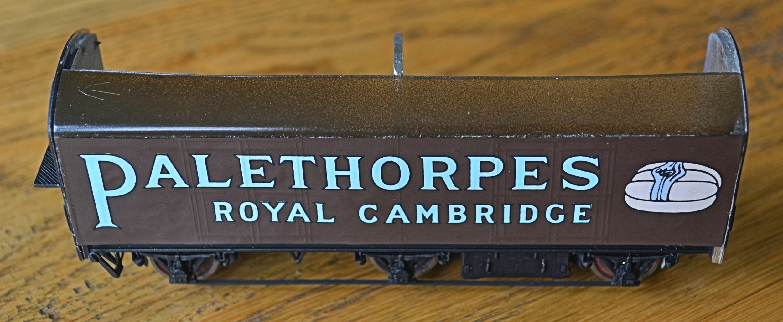
The sides were cut from their sheet with a sharp scalpel and a steel rule. It was apparent that they were not wholly square and so had to be cut slightly smaller than required. They were then attached to the acetate shell with contact adhesive. Great care was required for this as only one chance per side was possible: a mistake and the grip of this adhesive is so fierce that adjustment is impossible. So far, so good.
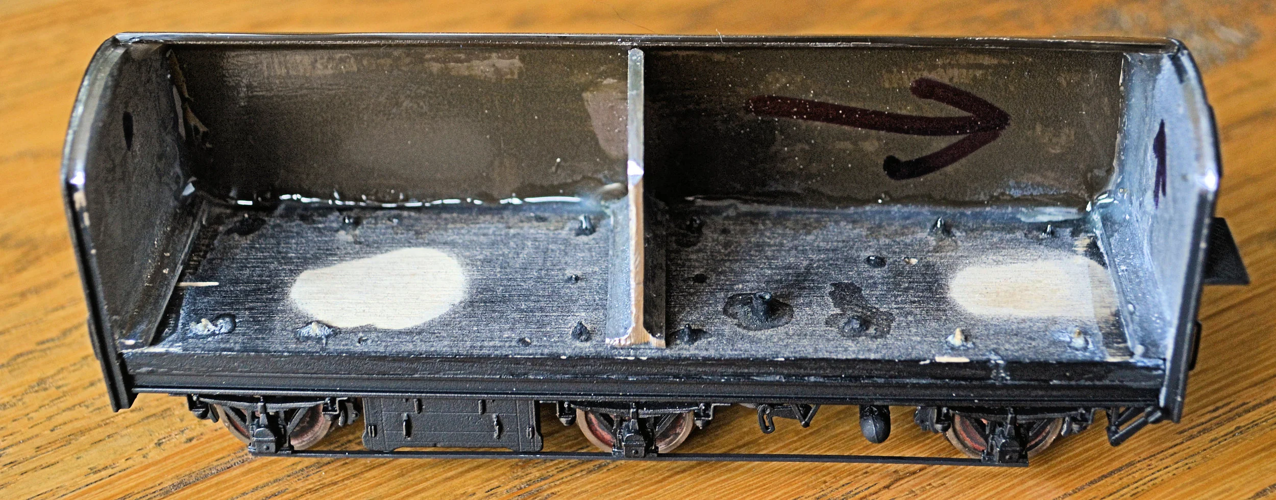
The roof was then cut from plastic card and shaped in the usual way using boiling water. A dry run followed, fitting the body and roof to the chassis and ends, but this immediately showed a significant mis-match: the roof dimensions were too small and the printed sides aligned differently on each side. This was a significant problem and something that I had feared. The only solution was drastic surgery. The body shell was cut into three pieces lengthways and the middle cut section cut again to make it narrower. The photographs explain this. The sides were then attached to the body individually, initially tacked with superglue and the joints then reinforced from inside with epoxy resin. Assembling the body in this way allowed for further adjustment and, importantly, invisibly securing the bottom of the sides from the inside. Held fast by epoxy glue, no further reinforcement was required. The thin centre section was then attached to support the top of the top when later fitted.
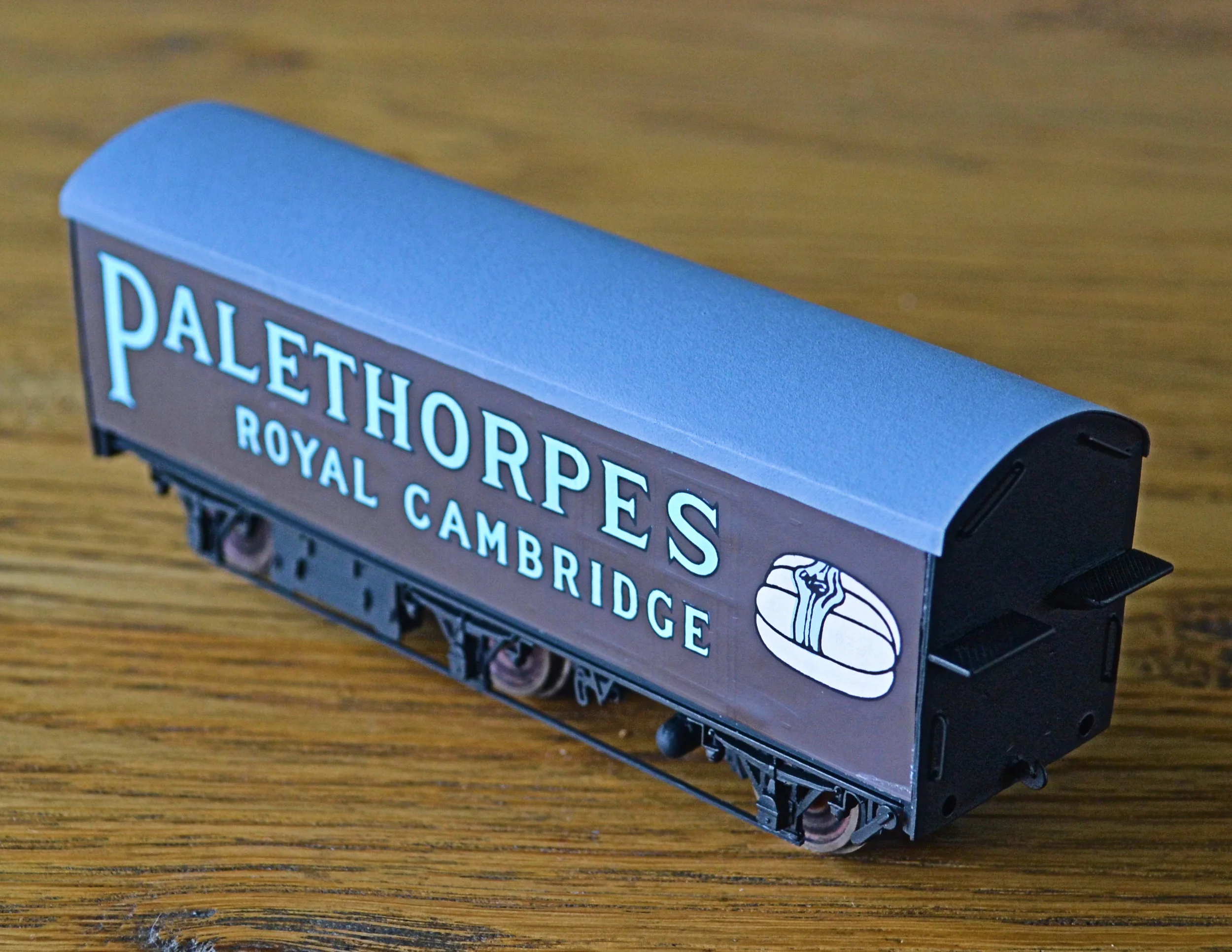
The original plastic roof set aside, a dummy roof was next cut from paper, increasing by several mm. the measurement of the original and it was offered up to the body. The sides were cut back in stages until a satisfactory fit was obtained and it was then used as a template for the final heavy card roof. I tried using plastic card but, because of the profile, could not achieve the necessary fit.
You’ll notice that the roof sides have to continue down the sides of the wagon for 1.5mm. This was cosmetically necessary to cover the tops of the printed overlays which, for reasons described above, had to be cut down very slightly. Once weathered, this will not detract from the model visually.
A number of further small tasks will lead to completion: steps will be added to the solebars under the doors, buffers will be fitted, rain strips fabricated, a ladder and an ice box fitted and couplings devised. Some areas of black paintwork will then be tidied up and the roof and underframe weathered.
With steps, couplings, buffers, ladder, ice-box and rain strips now added, the model is more or less complete. Once the various washes have dried, I'll weather finally with some powders [the roof, particularly]. I must source some appropriate GWR roundels and numbers also.
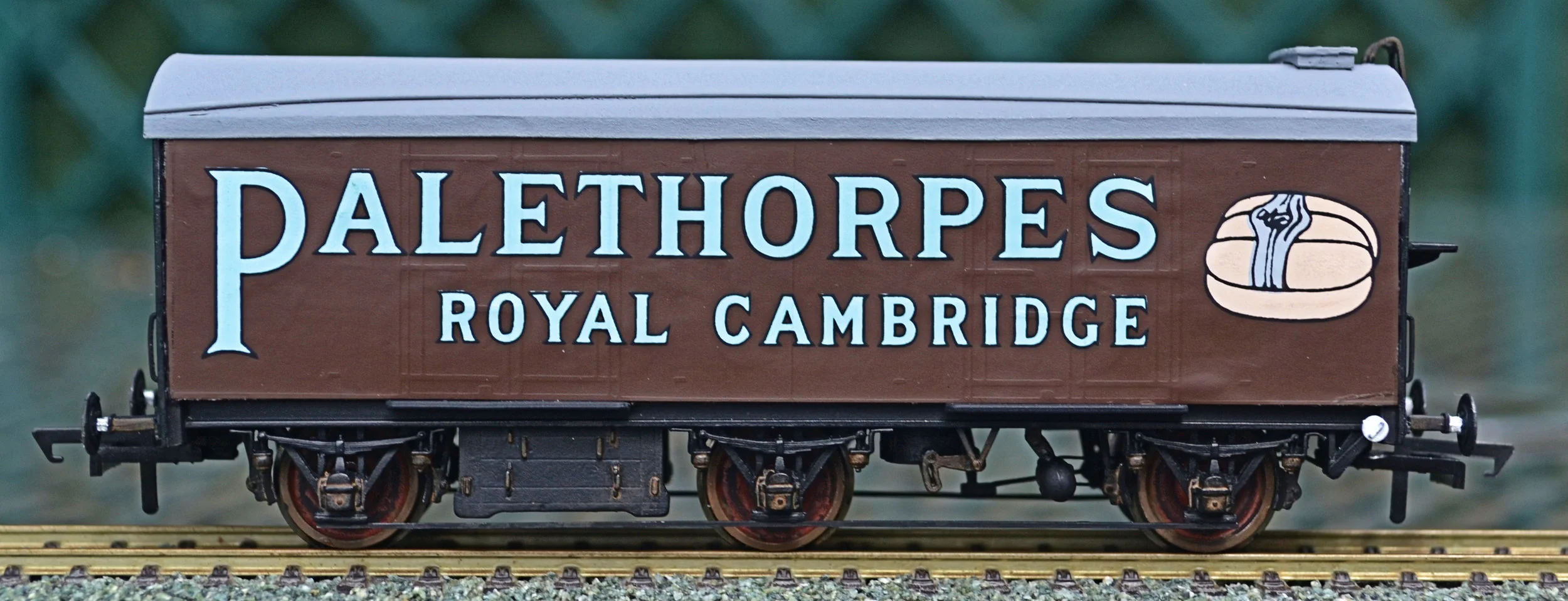
I had forgotten just how fiddley card roofs and rain strips were, particularly the rain strips [I decided that one each side was quite enough!]. This was a hugely enjoyable build however, a real return to typical modelling practice three or four decades ago and the end result, all things considered, is not too bad. Very little touching-up of the sides was necessary, for those few small scuff and mistings caused by super-glue, acrylic Burnt Sienna and Black mixed up to almost the same shade: it's not noticeable unless you know where to look.
And after a little weathering with powders, the roof toned down and rust added to the iron work....


