A GWR four wheel All Third Brake to Dia. T20
An easy ‘how to’ Ratio kit-bash

Images of this very small class of coaches are extremely rare and given that the last example was scrapped in the mid-30s, probably no more exist that are yet to be published. This image was found during a Google search and shows a model made at least 50 years ago from Ratio parts [note the metal Hornby Dublo-type couplings]. The aim of this project will be to show you how to produce a rather less crude model of a T20 Brake third relatively simply and inexpensively.
For decades now, and certainly for over 50 years, unless you were prepared to model in etched brass, Ratio made the only available kits for GWR four-wheel coaching stock. They are quite close to their prototypes also, which makes them attractive to finer-scale modellers as detailing them is well within the reach of most. Keyser also manufactured some GWR coach kits in white metal, but their four and six-wheel models were extremely heavy and needed a great deal of work to persuade them to run true with the parts as supplied [and only their six-wheel Clerestory Tri-Compo was really close to prototype*]. The Ratio kits go together easily and quickly, and when introduced they soon became ubiquitous. They continue to be available too, of course, and remain as popular for building as they come as for kit-bashing.
*shown elsewhere on this workbench
This build utilises parts from three scrap Ratio coaches, an All Third and two Brake Thirds, along with scrap plastic card, etc, and aims to produce a recognisable Dia. T20 Brake Third, an attractive and rarely seen short brake with passenger compartments at either end. It will be somewhat dimensionally challenged in that the roof is not quite of the correct profile and the length is nearly 4mm over: it will look just like a T20 Brake though, and that’s good enough for me! Ten of these coaches were built in 1882 and this one, No 907, soldiered on as the last of its class until scrapping in 1935.
In fairness, a far easier way of constructing this coach would have been to have purchased a Shirescenes etched brass overlay set for about £12 and fitted it to the side of a Ratio All Third coach. Job done. But where’s the fun in that?!!
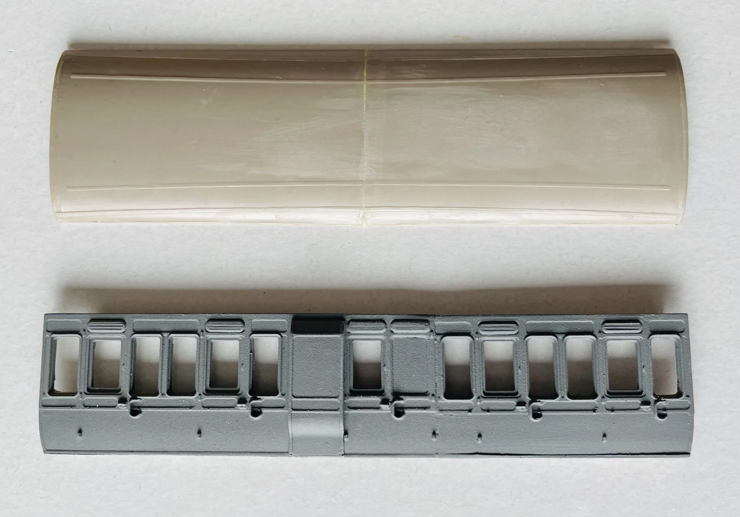
The starting point:
This next photo below shows the two sides used in the cut and, under them, the pieces to be joined after the cuts have been made. The centre Guard’s compartment comes from the left end of the Brake Third, the bottom left section again from the Brake Third and the bottom right from the All Third. Cutting the parts is straightforward with care: use a very sharp, fine razor saw with a mitre box and cut so that the parts to be used are initially wider than required. This allows each part to be then sanded back and continually offered up until as near a perfect join as possible is achieved. You may still have to apply a sliver of filler though.
The next task looks daunting but is not and only requires a little patience. The right-hand door of the guard’s compartment should be panelled without a window. Consequently, the existing window requires filling. To do this easily, first use a sharp scalpel to carefully pare back the moulded droplight until you have enlarged the opening back to just the inner edge of the window frame. Then, place a piece of plastic card behind the moulding and, using a very sharp pencil, draw around the inside of the window frame. This will provide a neat template for the new panel. Now use some Xuron shears or similar to cut away the surplus plastic, stopping when you are about 2mm all around from the template line. Offer up the piece to see how much more you need to remove before it will fit. Use an emery nail board for the rest of the trimming, remembering to add a radius at each corner. The emery board will only remove a little at each pass and, in this way, you should be able to achieve a perfect fit. Both of mine were good interference fits, but I still glued them into place from behind with liquid adhesive. The photo shows the completed job quite clearly [and the pencil marks]. If you remove too much plastic however, either start again or just glue the panel in place and then apply a little filler to the gap. I found that each side could be completed in about ten minutes.
It is now time to make any last minute adjustments to the edges of the three parts to be glued together to form the new side. Use the emery again board for this to avoid any risk of removing too much. Unless the parts are reinforced from behind, the joints themselves will be insufficiently strong to tolerate handling. I used a strip of 2mm square rod glued to the top and bottom of the inside to strengthen the joints and add rigidity. The photo below shows this and note that the bottom strip of rod is glued directly above the ridge on the bottom of the side: this will double as the new fixing point for the floor/chassis.

The next photo shows the three pieces of one of the sides glued together and set aside to cure. The lower right section has had some white .5mm rod added to its base to repair the panelling. This was glued on and then gently sanded back to match the profile of the panelling at the bottom of the left hand side. Both sides should now be a strong single unit.

Next, once the sides are strong enough to handle and you are satisfied with the joints, spray each side with primer and set aside to dry. One of my sides was fine, the other required a sliver of filler to close the bottom of the joint where the right hand end joined the guard’s compartment and a little also at the top of the door in the same place. You can see the gaps in the next photo. Filling it was a quick job however and it was soon fine. If you do use filler [I used Milliput], allow three or four hours at least to elapse before undertaking any sanding back. You may have to apply filler more than once to achieve a satisfactory finish. Just be patient.

The two sides can now be set aside to await their first coat of paint. Now, you’ll turn to the roof for the next bit of surgery. First, carefully sand away the gas lamp tops from the roof as you will need to fit replacements in different places later. If offered up against the sides, you’ll also notice that the original Brake Third roof is now too long to use and will require shortening. I removed 6mm from mine, cutting it out of the middle [and not the ends], but you should measure exactly the length of your sides and then remove from your roof just enough to leave the slightest overhang at each end of the coach: aim for a roof which is absolutely no more than 1mm longer than the coach body. Again, use a sharp, fine saw and a mitre box. Dress the cuts carefully with a fine emery board and then use the section removed to reinforce the joint from underneath [you’ll need to cut a few mm off the end of the section removed or it will foul the coach sides when the roof is finally fitted]. The photos shows the roof shortened and rejoined against a completed coach side and then the joined area sprayed with primer. The joint is exaggerated by the primer and should be all but invisible after two coats of matt black paint.


I chose next to give each of the sides their first application of paint, in this case, two coats of GWR cream. It’s better to start with the cream as masking it for the later application of chocolate is far easier than painting the sides the other way around: all you have to do is mask down to a line very slightly above the commode handles and the tape will remain flat. Do it the other way, and mask up to and over the commode handles and the tape will not easily lie flat and you risk a bleed. By the way, that’s a dog hair, not a crack, on the upper side! I won’t want to apply masking tape for a few days to allow the paint to cure fully and so will set the pieces aside and now turn to the chassis [which needs a lot of surgery also!].
For the chassis build, you can either use one already constructed from a scrap Brake Third [in which case you will need to dismantle it very carefully - and this will be difficult] or do as I did and use one unmade from a kit. The chassis should be assembled as per the instructions for the kit but, before commencing, the floor needs to be reduced in both length and width. For my build, I reduced each end to result in an overall length of 114mm. I then reduced the width by cutting back each side to arrive at an overall width of 26.5mm. The easiest way to achieve all of these reductions is to use a steel rule and sharp scalpel to score the cut line fairly deeply and then cut along it with some Xuron shears. It is surprisingly easy and accurate.
Note: if you are not using scrap sides for your build, but parts straight from the box, you will only have to reduce the overall length of your coach floor because the inside beading to take the floor will be undamaged and it can be inserted at its full width.
The sole bar and foot board mouldings will need to be cut back similarly and this is best done before attaching them to the floor moulding. And whilst on the subject of the sole bar and footboard mouldings, remember that these are incredibly fragile and very, very difficult to repair once broken. Great care must be taken when removing them from their sprues. All of this done, open up the holes in the axle boxes to accept some brass wheel bearings [make sure they fit flush and attach with superglue] and then continue to construct the chassis as normal.
Once the chassis has been completed, and the glue has cured sufficiently for the more-fragile parts to be handled, it is worth having a dry run with the wheels to ensure that they do not bind. There are three places where this can happen: the brake shoes may catch the tyres and so need gently opening out; the wheel make rub on the bottom of the brake shoe moulding and so require that part to be cut away; the sole-bars may bend inwards too far, preventing the pinpoint axles from spinning freely in their bearings, and so need gently bending out. Or it could be a combination of all three! All of these problems are resolvable with a little care. Once you have free-running wheels, remove them again, cover the brass bearings with masking tape or Blutak and they spray the whole unit matt black. make sure that you cover the hard to reach bits too, like the underside of the gas cylinder. You can, of course, brush paint if you’d rather. When the chassis has dried, insert the wheels and it should look like this.

Note: apart from fitting metal wheels [essential], the entire coach is plastic and, so, quite light. This may create some problems when running and fitting ballast is a sensible option. There are many ways to do this and some modellers glue coins or scrap lead sheet to the floor. I use [and can recommend] self-adhesive tyre weights. These are easily sourced via eBay and two 5 gram weights stuck between the wheels give additional low down weight to aid stability and running. Once fixed, they are inobtrusive.

With the chassis completed, it was set to one side and attention returned to painting the body sides. The next photo [left] shows the sides after their application of chocolate and with the door droplights painted dark brown. One or two raggedy areas will be cleared up by brush-painting with aerosol paint in due course and the glossy lower half will lose its sheen under stain varnish.
The repanelled window opposite the Guard’s door looks quite effective now, and original.
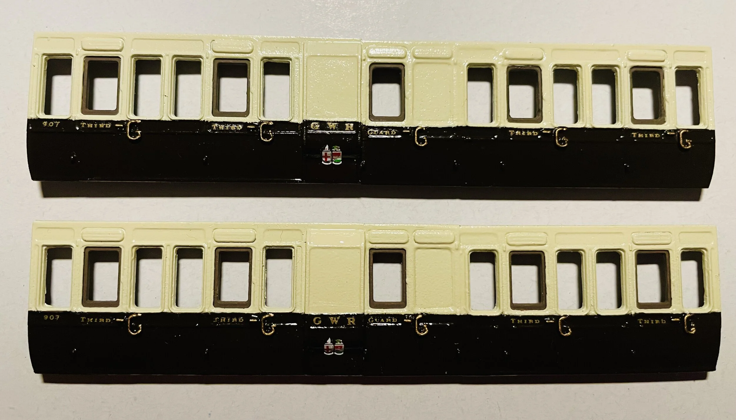
The photo opposite shows the sides now lettered and with the brass-work picked out. I had intended bow-penning in a gold line along the boundary of the chocolate and cream, but the raised nature of the mouldings in that area made it impossible: had I tried, capillary action would have drawn the paint away and along the various mouldings, ruining the finish.
The next job, before applying the glazing from the other side, is to spray the coach sides with satin varnish to seal the transfers and the soft brass paint. I have also sprayed the coach ends matt black, and set them aside for attaching later on.
With the sides now finished in livery terms, there is no sign of the various joins anywhere.
With the sides now glazed and the painted ends ready for fixing, the four parts were attached to produce the box of the body. Because the ends were butt-joints inside the sides, and so potentially flimsy, when the box joints had dried they were reinforced from inside with epoxy cement to form a stronger unit.
One small area at one end required a little filler to close up a gap, but that will wait until the roof has been attached as, doubtless, more filler will be required there as well.

The interior detail is a simple affair of plastic card for partitions and scrap wood and paper for the seating. Interior detail is necessary but as it will be difficult to see clearly, a basic finish is quite acceptable: it just has to look right.
With these internal fittings now secured, a card roof was overlaid [not shown] and the roof was then glued in place using epoxy cement. After fully curing, it was clear that a couple of areas would require some filler to close up gaps and seams, hardly surprising given that the various parts all came from different sources and the roof has suffered a little in the hands of its previous owner. The photos below show this: one of the sides needs a little filler to close the gap between it and the roof at the ends and both of the ends require filler to smooth out the arc at the top of the ends and the underside of the roof.
Before applying the filler however, the body had its buffers and dummy coupling hooks applied and was then attached to the chassis with epoxy cement. A little packing [microstrip] was required at one end and glued onto the upper floor of the chassis to ensure that the body sat squarely. Set aside to cure for a couple of hours, filler [Milliput] was then applied to the various gaps and seams and the whole unit left alone for a day to harden thoroughly.


With everything now solidly glued, the ends were resprayed in matt black, vacuum pipes and Bachmann couplings attached and the coach build was complete.

And seen here sitting in Downton Road station with its All Third partner [a unaltered straight-out-of-the-box build]….
