Some recent[ish] loco builds
Ex-Midland Railway 2000 Class ‘Flatiron’ 0-6-4 tank
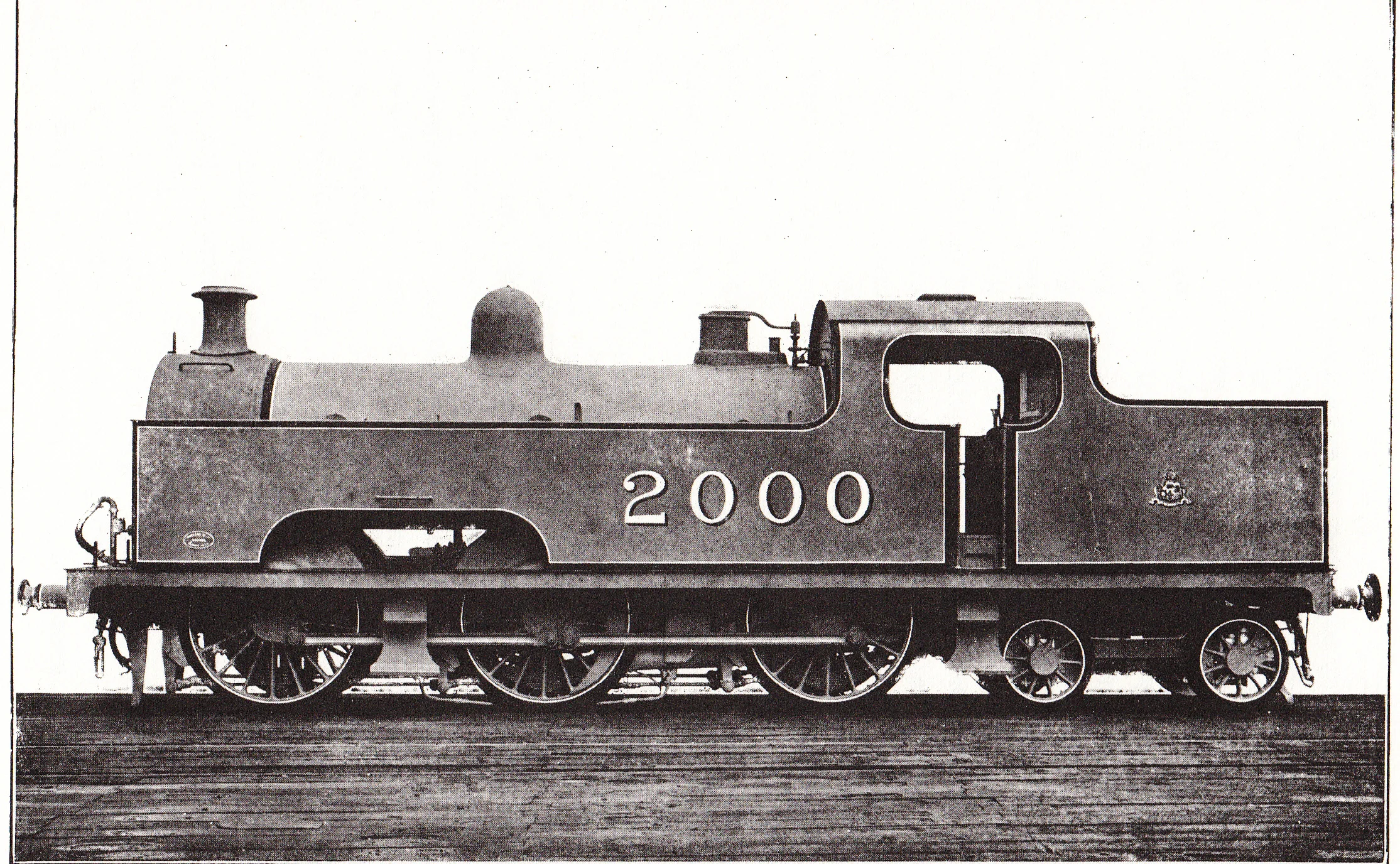
Opposite [courtesy of Wikipedia, with thanks], the first of Richard Deeley’s class of 40 ‘Flatiron’ tanks. Building commenced in 1907 but after not terribly distinguished careers [which saw a number of accidents] all had gone to the torch before the last War.
This model was assembled from an old white-metal Finecast kit [body only] and runs on a largely scratch-built chassis. It is powered by a Portescap motor driving Romford wheels. The chassis required re-building three times [and a change of motor] before it started to run acceptably. The body is built as it came although some added detail has been applied to improve it appearance. The crew are from ModelU.
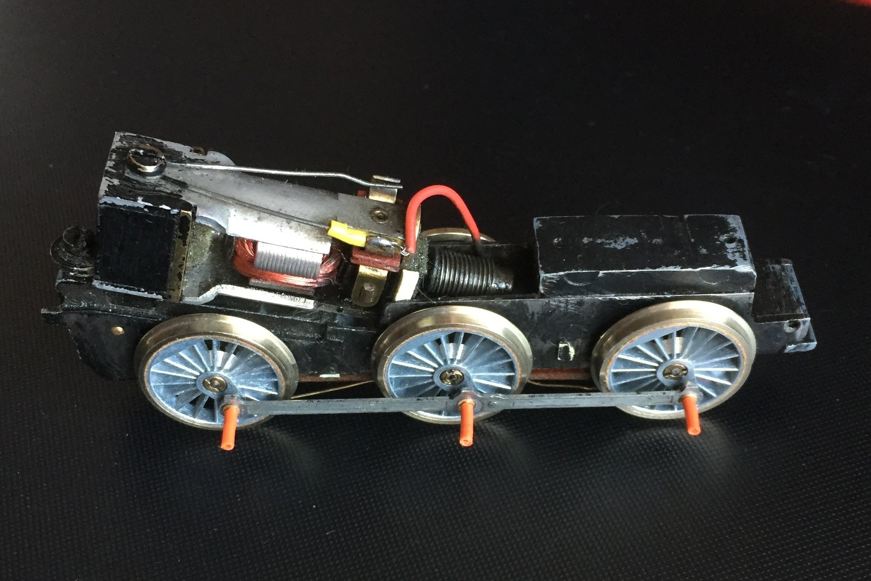
The first chassis build, using components from the bits-box. The chassis block was formed from two brass plate frames attached to front and rear spacers cut from an old Triang Jinty chassis. It ran, just, and is really a bit of a mess….
A rebuild was obviously on the cards, and a Portescap RG4 motor with an integral gear box was substituted for the XO4 type shown opposite. A little tinkering and it ran well. With the running gear sorted, attention could be given to constructing the body.

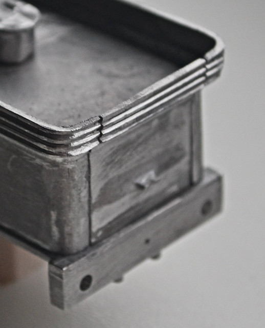
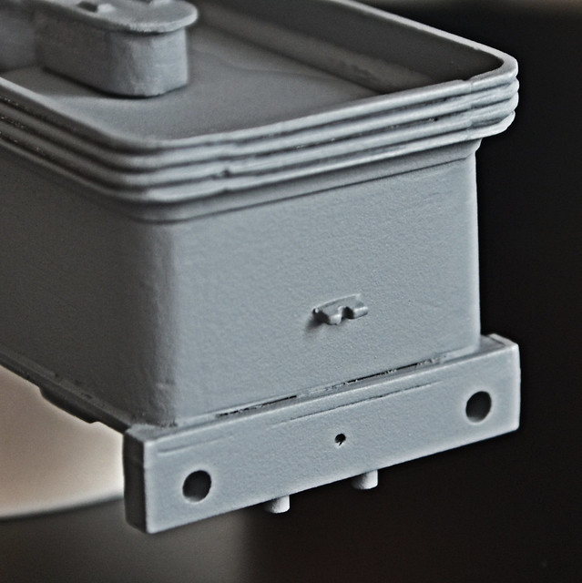
Above is the later chassis, an altogether neater and more handsome affair. It is shown with the wheels and rods painted and the rear bogie fitted [although adjusted later].
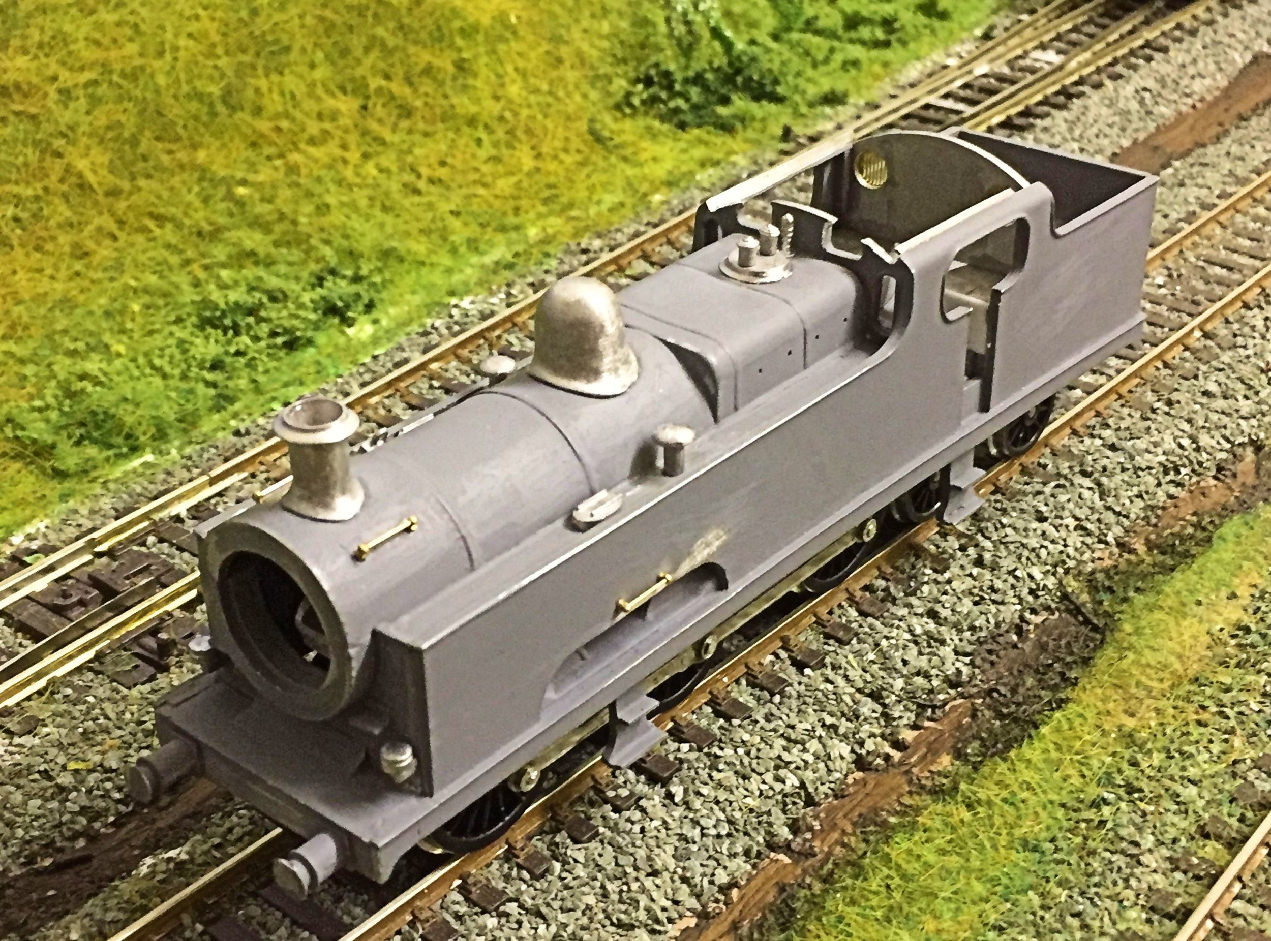
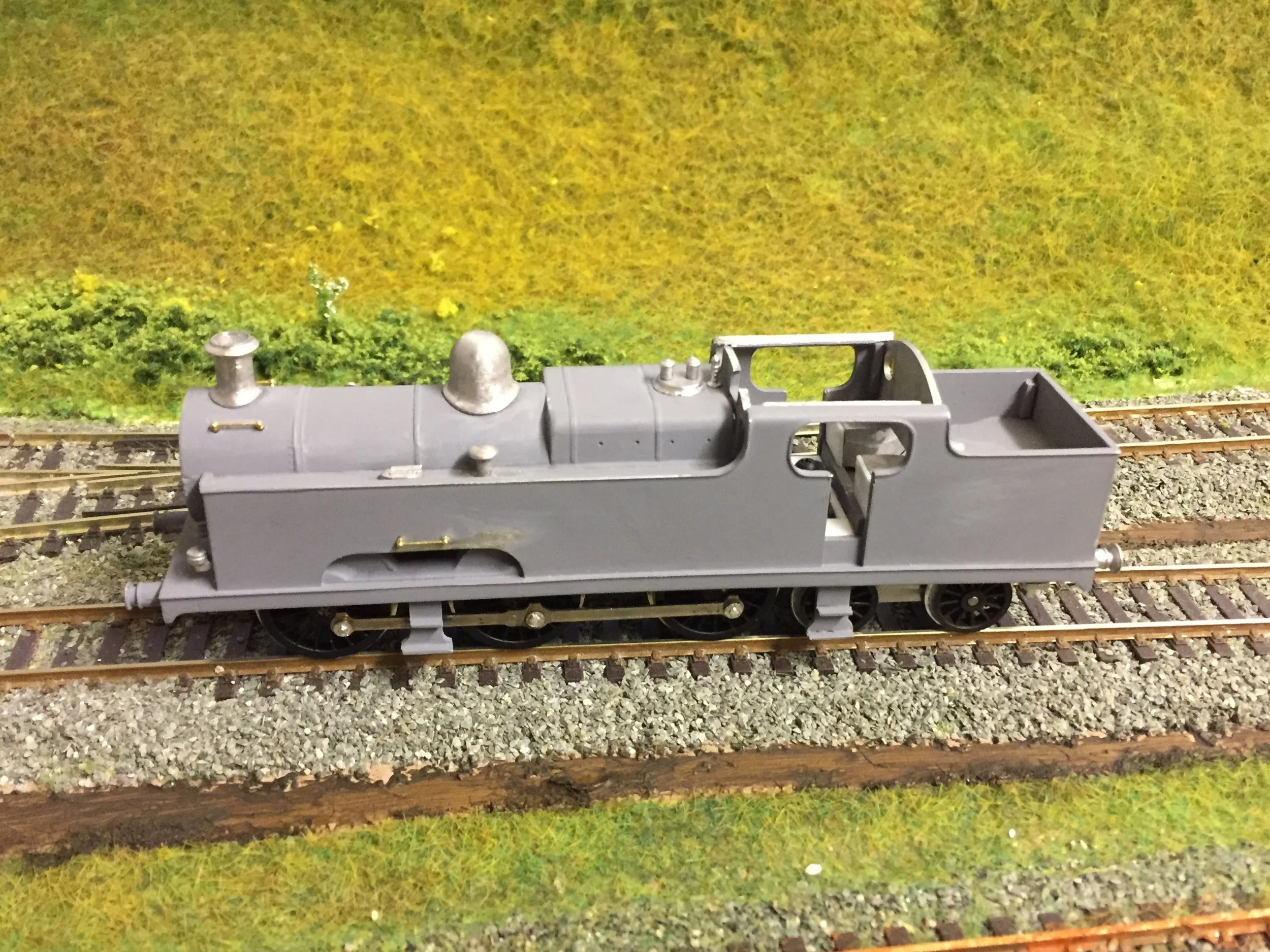
Above, two photos of the body at an early stage during its construction. Two-part epoxy glue was used and a first coat of primer has been laid on to check for any need for further filler. Some of the detail castings have also just been attached. A great deal of fettling and filler was required to obtain a square and acceptable fit of the various body parts. Not unusual for old white-metal builds though.
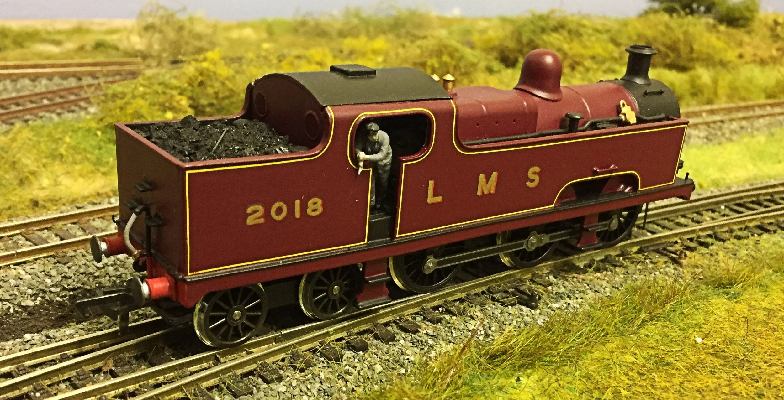
By now though, the characteristic outline of the Flatiron, with its ‘hole in the wall’, is quite unmistakeable.
With the body complete, the whole casting was primed again and then sprayed with Halfords’ Rover Damask Red, a near-enough approximation of LMS Crimson for me. The black areas were hand-painted and the lining, numbering and lettering applied with Pressfix decals.
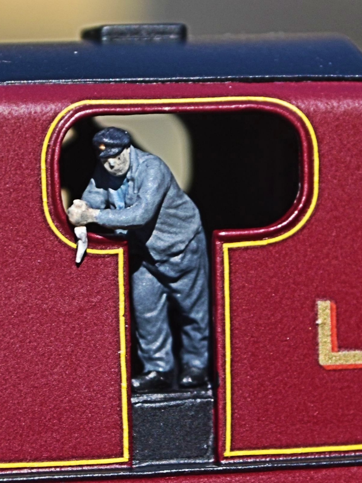
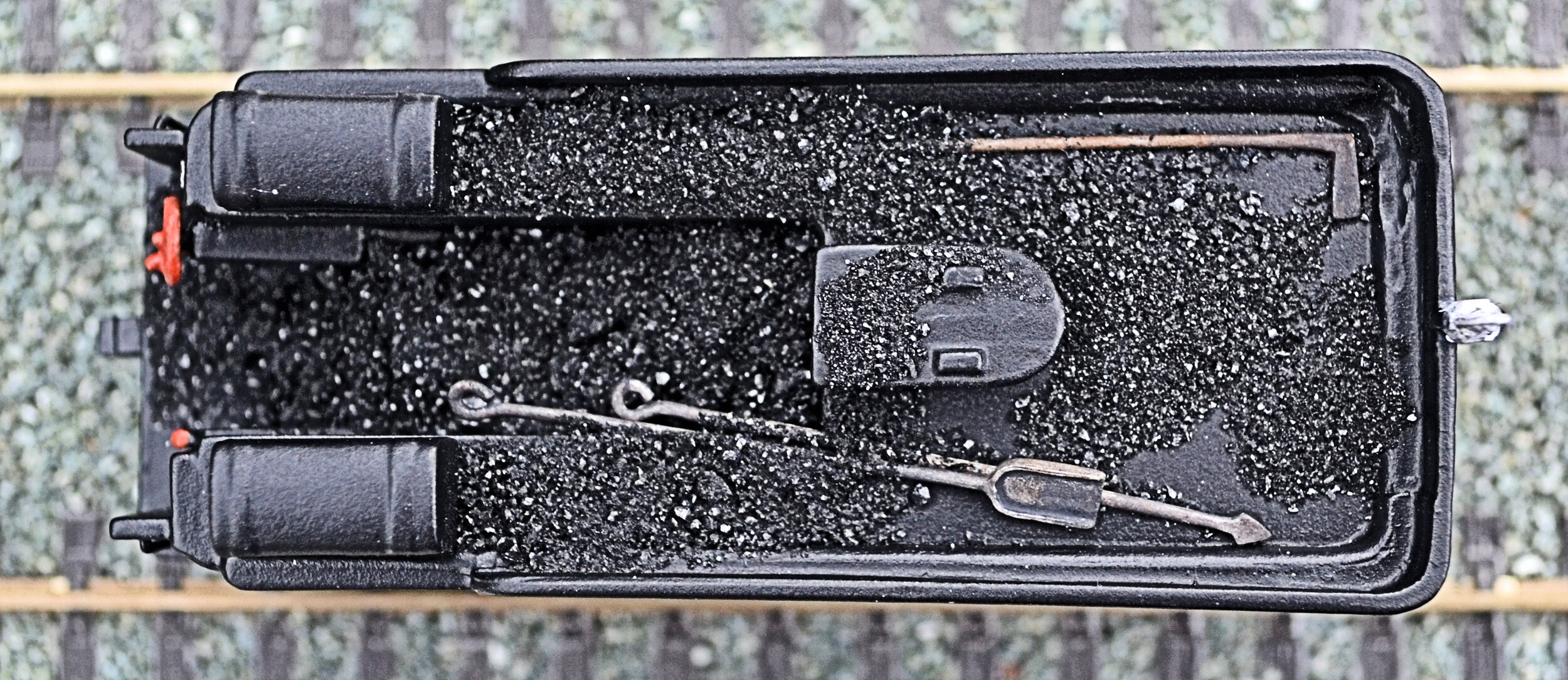
The crew [the driver opposite holds an oily rag]was painted up and attached to a plastic-card floor which had been inserted into the tank for that purpose. The interior of the cab was painted cream and the bunker filled with coal. Etched spectacle bars were attached to the rear cab windows to protect them from breakage through over-enthusiastic coaling of the bunker. Lamp irons have also been attached.
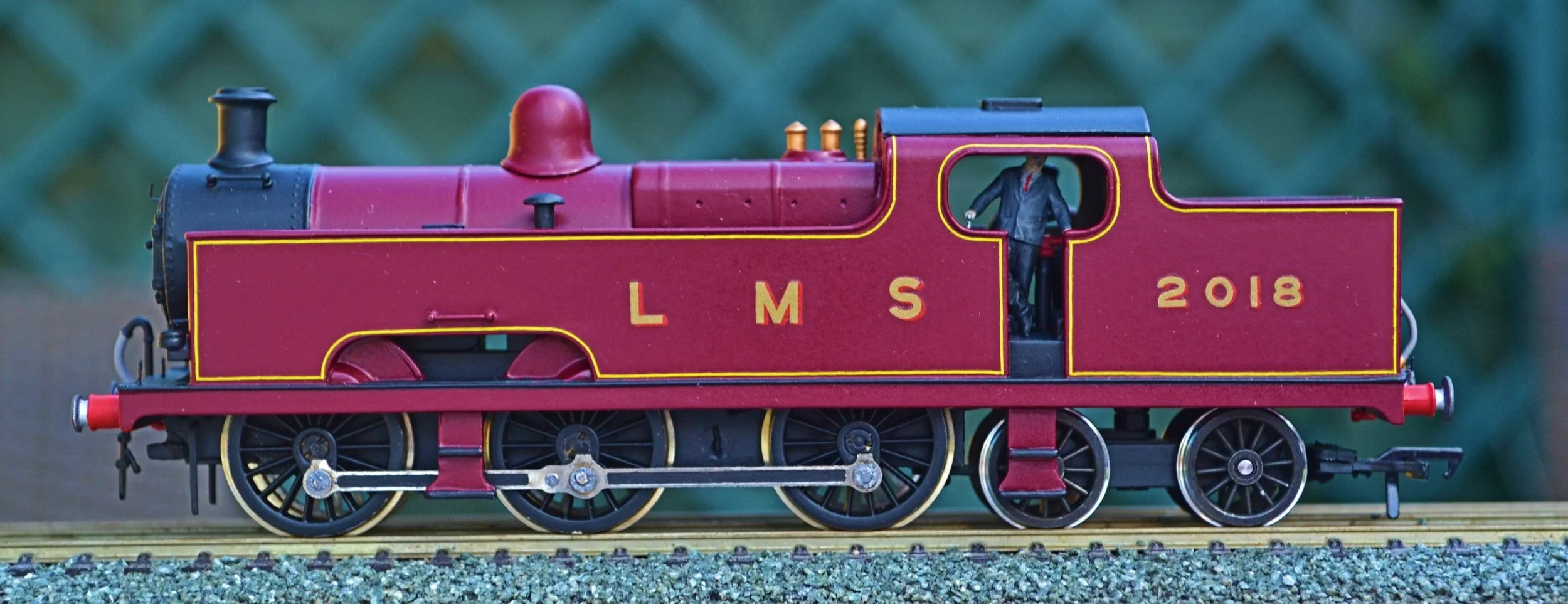
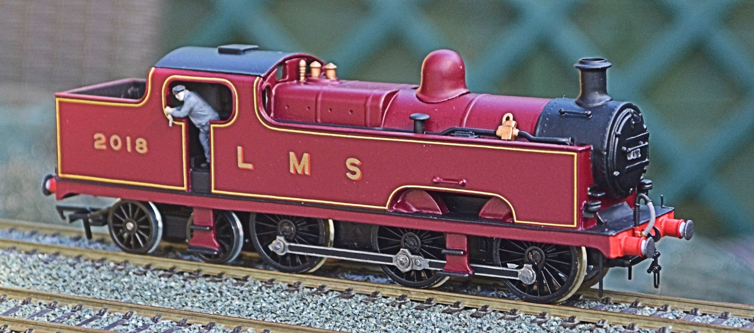
The above photos show the first fit of all of the completed parts. The tank ran well but I was unhappy with the positioning of the rear bogie. Using the components supplied in the kit, the bogie sat far too close to the driving wheels. A new bracket was fashioned out of brass scrap and, as the photo below shows, the bogie now sits further back, looking far happier for it, too.
Elsewhere in my workbench is a description for a build of the first two of three Keyser white-metal ex-LNWR six-wheel coaches. These are so heavy that the Flatiron is the only loco I have that is really comfortable pulling them!
Ex-London & North-Western Railway 18 Inch Goods: the ‘Cauliflower’ Class 0-6-0 tender loco

By Ben Brooksbank, CC BY-SA 2.0, https://commons.wikimedia.org/w/index.php?curid=18419013
The photograph opposite shows a member of the class in Workington, in BR days, towards the end of its long working life. It ran both passenger and freight traffic on the Cockermouth, Kewick and Penrith line for most of its time, and was withdrawn in September 1953. The ‘Cauliflowers’ [so called because of the LNWR’s flowery crest on their tenders] were designed by Francis Webb and comprised a class of 310 powerful locos. Building commenced in 1880 and ceased in 1902. All were gone by 1955.
This build, another white-metal model, was a 50 year old George E Mellor kit. It is powered by an Anchoridge DS10 motor and runs on Romford wheels. It was constructed pretty much from the box although some replacement and additional brass and etched parts were added to improve the detail.
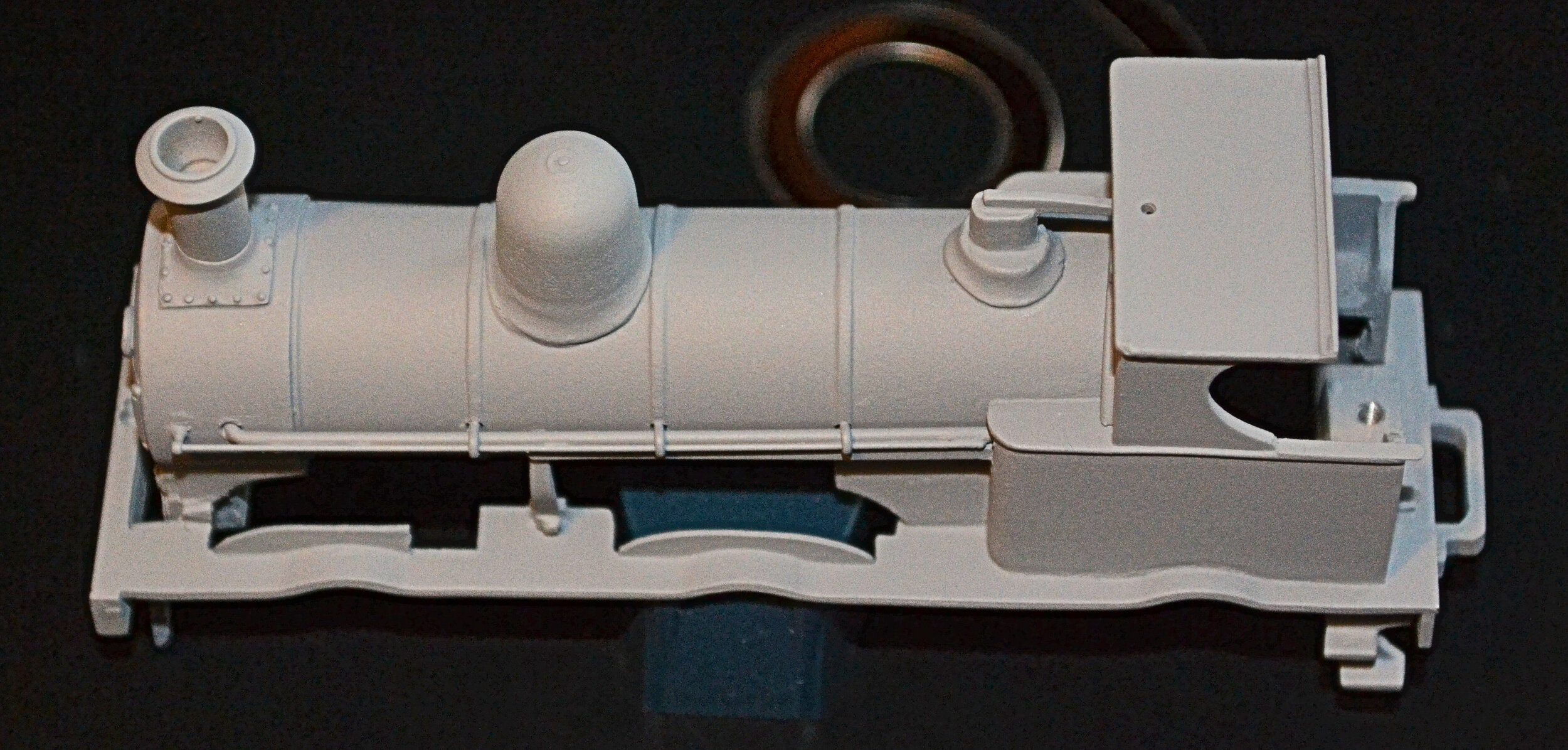
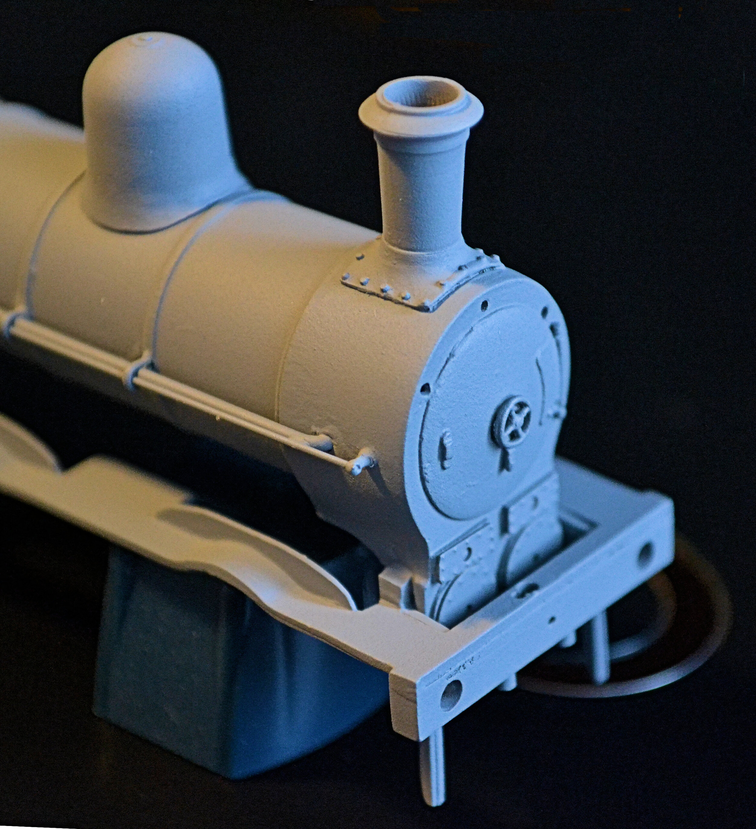
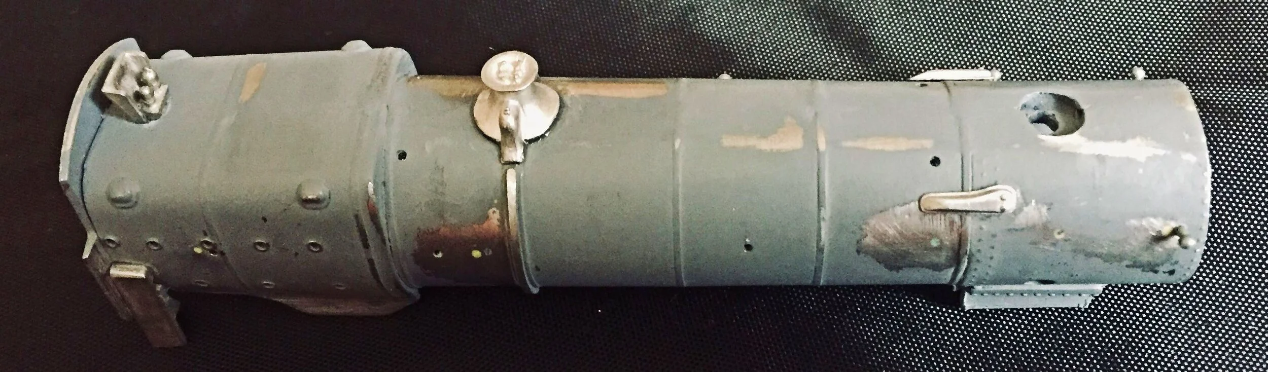
Being an old white-metal kit, the castings presented the usual problems of distortion and poor fit. The boiler was particularly problematic with highly visible and prominent seams requiring filling along both its top and bottom. Any failure to remedy this would have rendered the build void: there would have been no point in continuing. I used two-part epoxy resin to manage this, over-filling both seams, allowing it to cure thoroughly and then [arduously] sanding back. The photos below show a ‘before and after’, with the visible top seam completely eliminated.


The back end of the tender presented similar difficulties, although Milliput epoxy filler was used on this occasion. The coal rails were particularly difficult to line up and careful filing took it about as far as was possible. When later detailed, painted black and filled with coal it was all but unnoticeable.
The tender was the first part of the model to be completed. It is a heavy but free-running model and required additional detailing to make it look all but basic. The W-irons are incorrectly spaced also, making the wheelbase look just a little odd. This does not affect the running properties but, for me, jars just a little. In hindsight, it may have been possible to have cut up the lower chassis to rectify this prior to building, but it would have been extremely difficult and may just have made matters worse. The lamp-irons, coupling hook and hand rails are bits-box additions. The wheels came with the kit but they run in brass top-hat bearings.


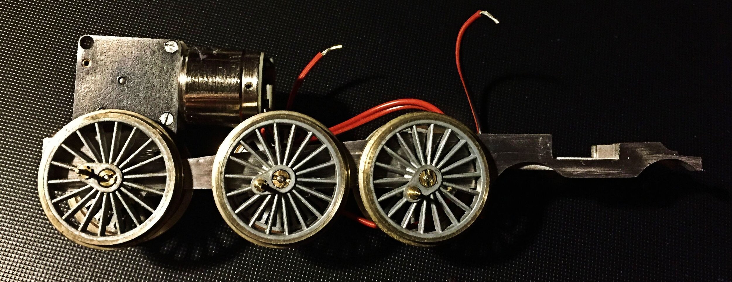
With the tender put to one side to await painting, later, work commenced on the loco body and chassis. The chassis was a simple white metal casting which screwed up into the body once complete. This type of chassis is relatively unsophisticated and can be problematic if the axle holes have not been drilled carefully. In this case, all was fine however and the unit assembled quite easily, running freely immediately. The photo alongside shows the chassis at an early stage, checking for fit and clearance. very little adjustment was required within the body to avoid fouling. Below, the chassis complete and in place.

The body was assembled in my usual fashion. Once all parts had been dressed, two-part epoxy glue was used in the construction. I like this method as it avoids potential damage to the castings from a hot soldering iron and allows for final adjustment and jiggling before the glue cures. It also acts as a filler where necessary. Nevertheless, some filler was required in various places and Milliput was used [particularly around the joins between the cab sides and the boiler].
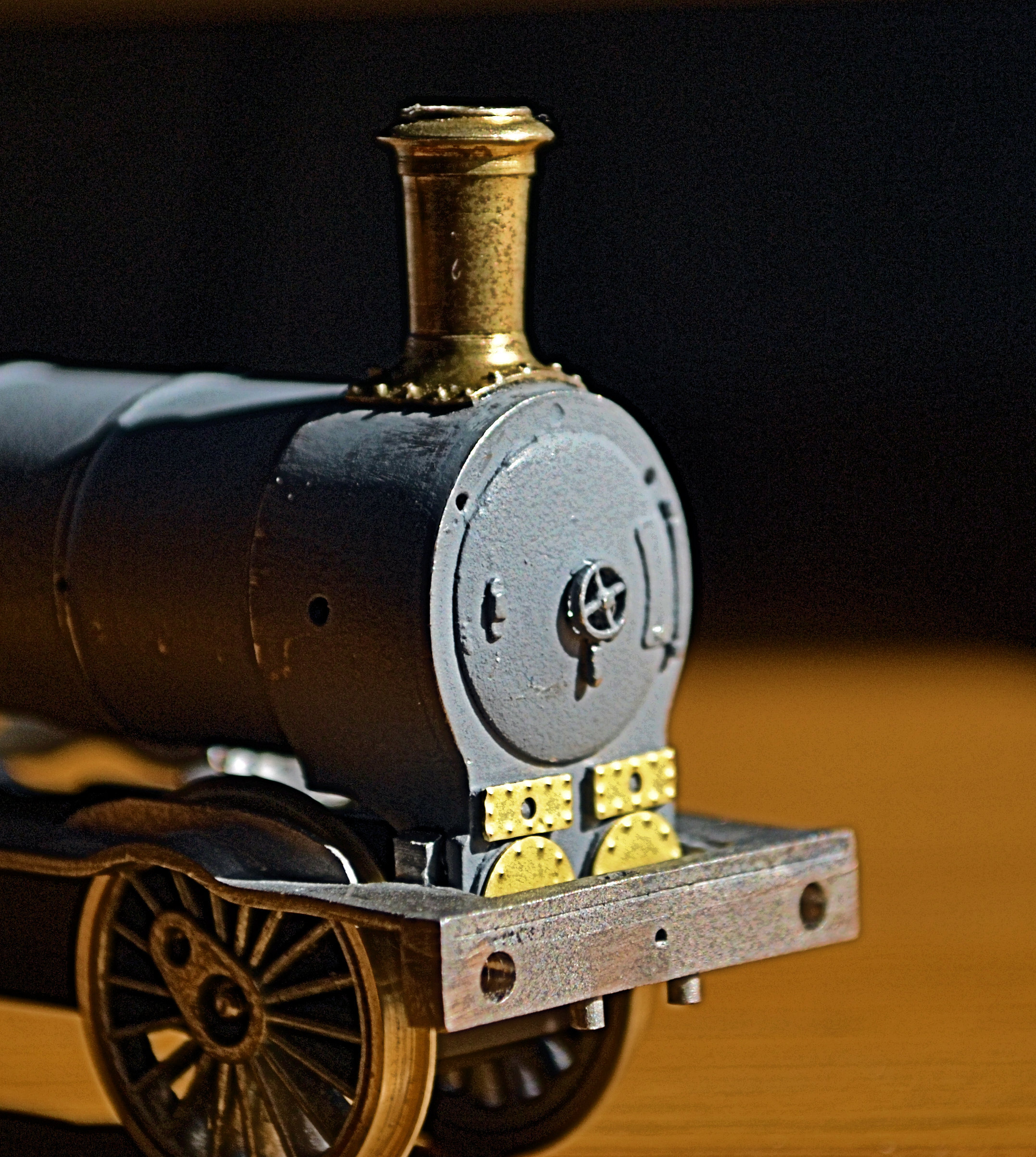
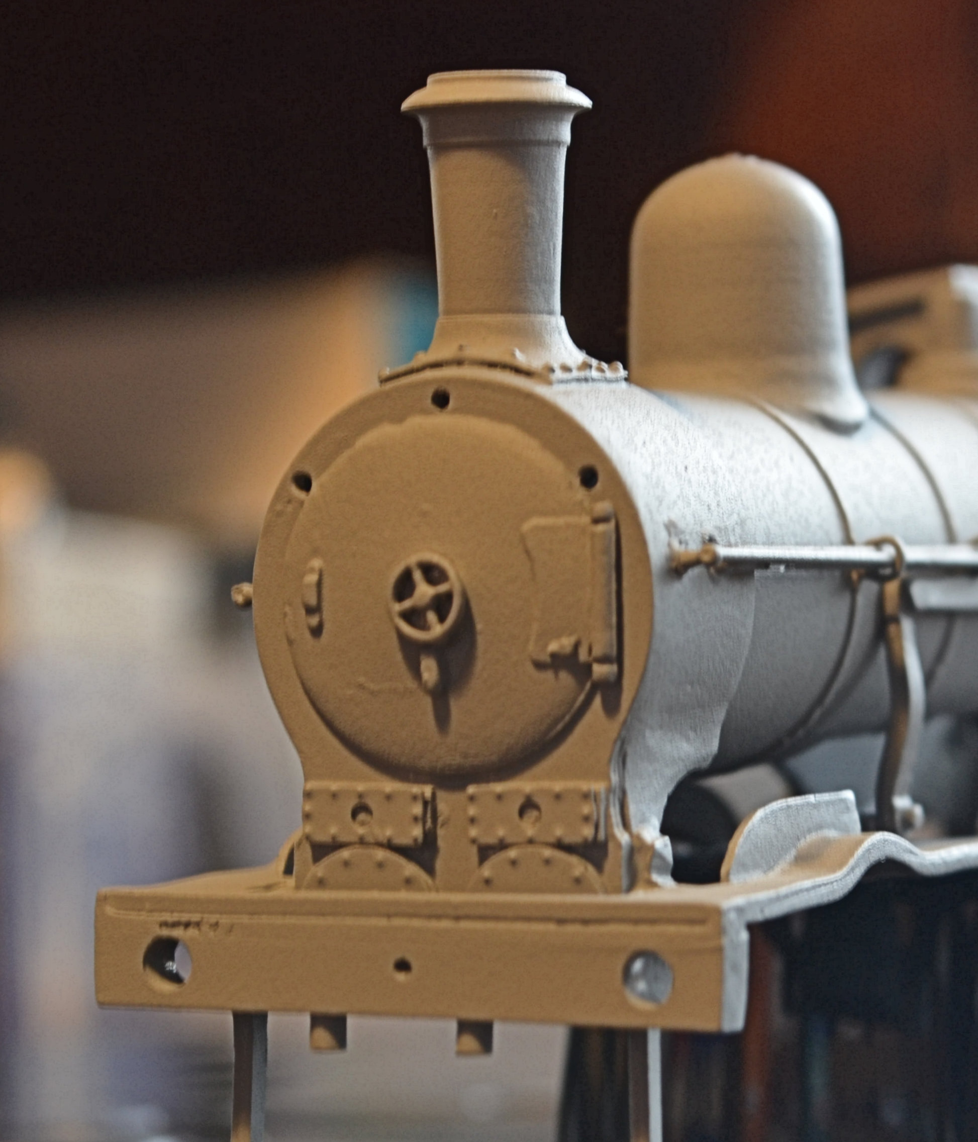
To add / improve detail, some after-market brass parts were fitted at this stage, a more accurate chimney and riveted cylinder covers. Both made a great deal of difference once in place. See above.

The only other addition to the body was some brass strip, applied to extend inwards, slightly, the rear-most splashers, so that they were properly in line with the running plate and also met the cab sides. These strips were attached with superglue and whilst they do change the profile of the splashers, they are not so noticeable when painted up.
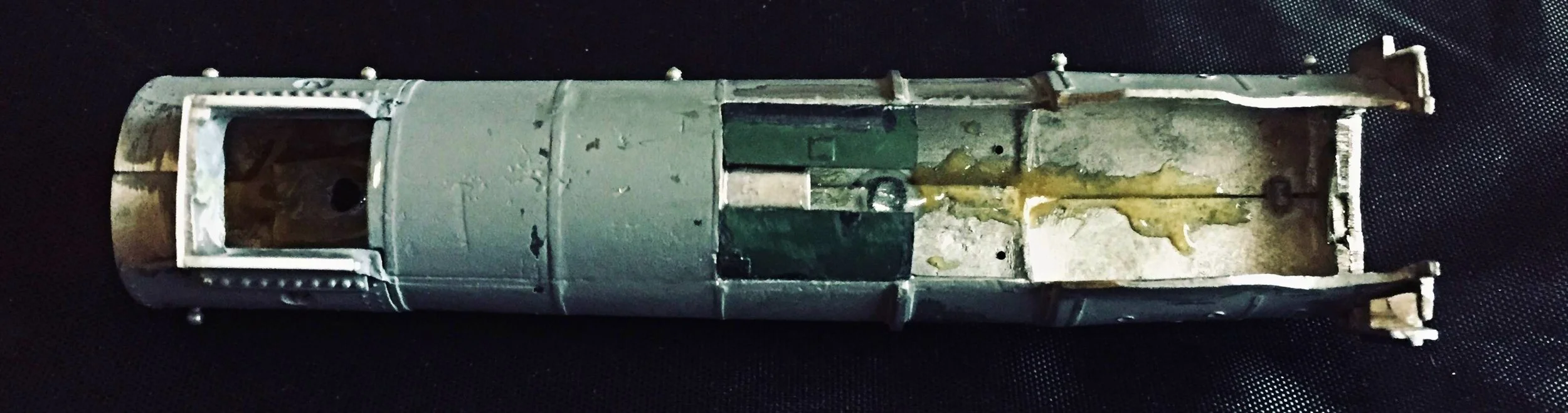
The photographs below shows the body in primer prior to fitting the splashers. The boiler-side pipework and handrails have been attached however [fiddly!]. A kit of relatively few parts, the only real difficulty presented by the body was ensuring that it sat fully square and level on the footplate / running plate casting. The smoke-box saddle area presented some problems, and a great deal of filing was required. Fortunately, there was too much metal there, not too little.
To complete the body, various final detail parts were added, including buffers and brake pipes, sand boxes and the reversing lever. The body was then primed once more and then sprayed satin black with the buffers, buffer beam and other detail parts being picked out in their appropriate colours. With all paint fully cured, lettering and numbering was applied with Pressfix decals. These were sealed in place by giving the body a light spray of satin varnish. The chassis [already completed and painted] was then screwed into place. the tender was detailed with coal and a lamp, and the cab backhead picked out and a crew glued into place. The backhead did not come with the kit but was found in the bits box. It was carefully trimmed so that it would fit around the slightly exposed Anchoridge motor: it, and the crew, do quite a good job of hiding it. The following set of photos show the completed model.


Great Western Railway 57XX class pannier tank : 5701
This next loco is a slightly earlier build, an old Wills white-metal 57XX Pannier Tank with a much-modified Bachmann cab to back-date the kit to the earliest version of the class. 5701 was built in January 1929 and withdrawn in January 1958 from Westbury. These tanks were iconic GWR locos, and if one includes the various sub-classes, over 800 were built. A great many of the class continue to run happliy in preservation. It was said of the GWR that if they had only these tanks and the Hall class locomotives, they could still have managed quite well.
No photos were taken during this build, but the model is powered by a Portescap motor and runs on Gibson wheels. It has been fitted with sprung buffers. This rather basic kit was further improved by adding lamp irons, some cab fittings, runs of piping and other plumbing, more accurate cab steps and sand boxes. The rear of the bunker has been fitted with fire iron hooks and tool, and the inevitable bucket.

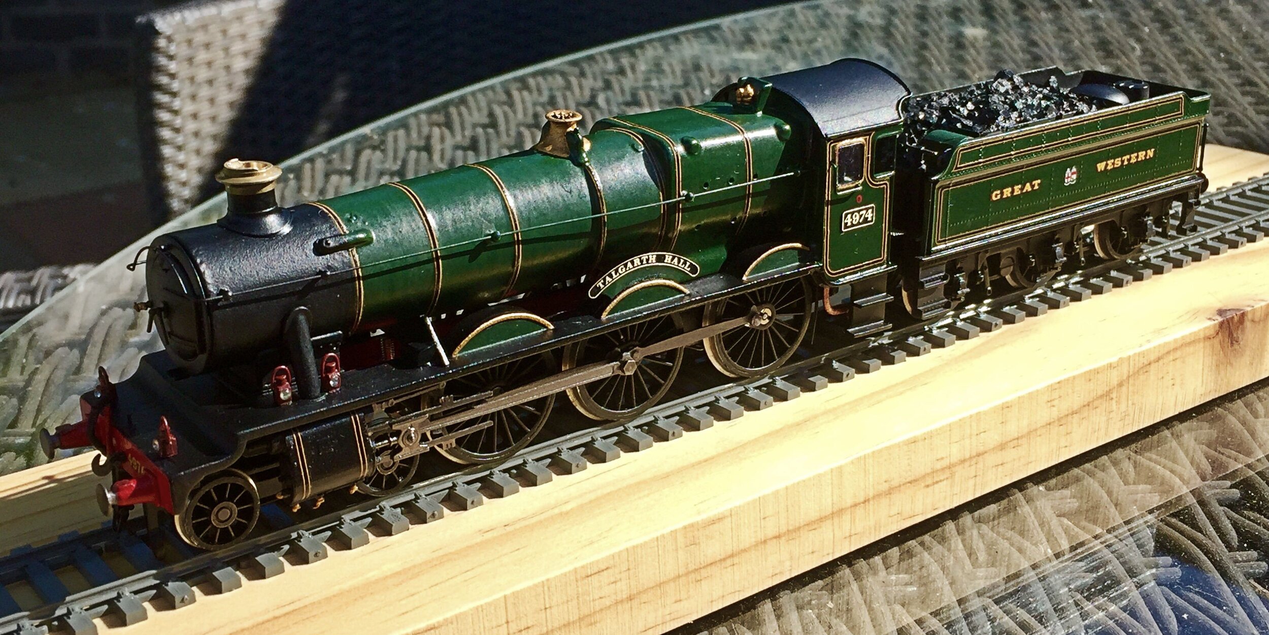
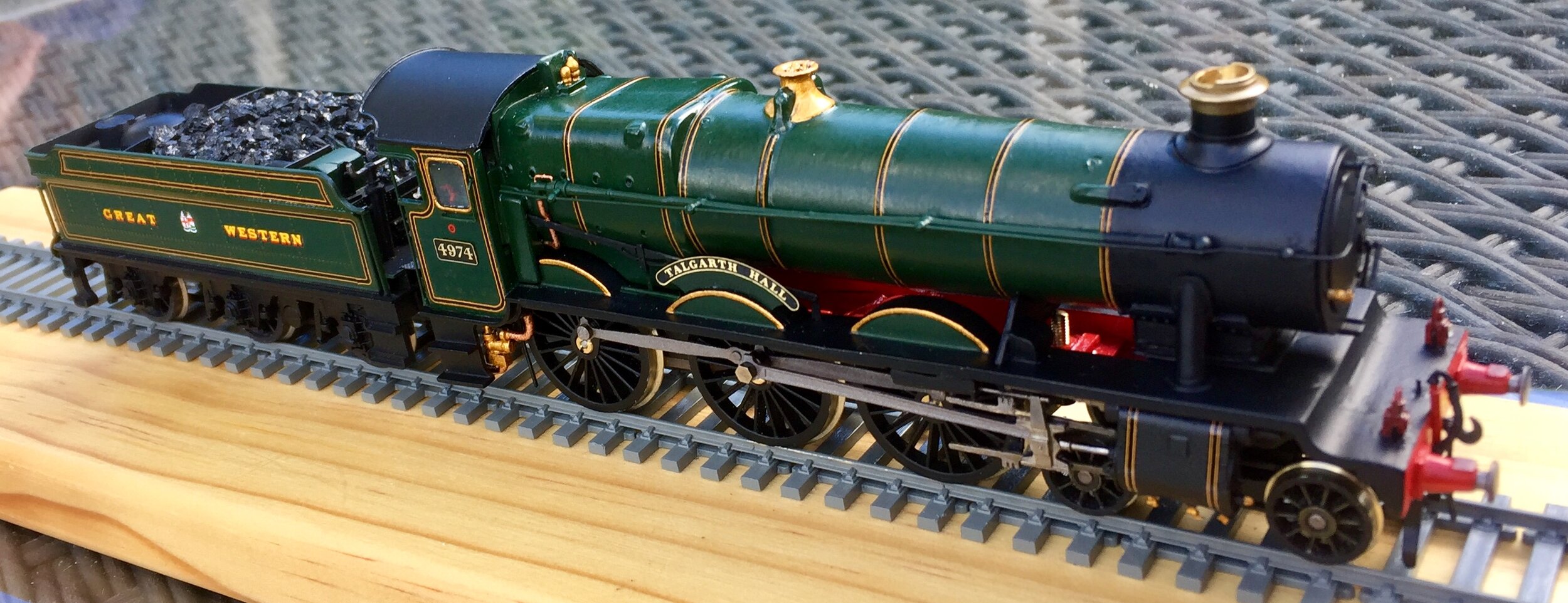
Great Western Railway ‘Hall’ Class loco : 4974 ‘Talgarth Hall

GWR Hall class loco, ‘Adderley Hall’, taken in photographic grey. Source currently unknown.
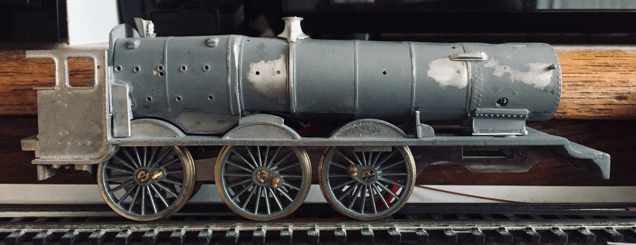
I bought an old Wills Finecast Hall kit some four years ago and have decided at last to build it as an entry into the club's 2020 modelling competition in early April. That was the intention, at any rate. This is, I think, the most problematic white metal kit I've attempted to date however and whilst it will get finished, there have been [and will continue to be] problems at absolutely every turn.
Here it is anyway:

Designed originally for mounting on a Triang B12 chassis, this would make the kit at least 50 years old. Included in the box was a white metal chassis block as well, designed to accept an XO3/4 motor. Obviously neither drive plan is acceptable and whilst I'll use the chassis block [which at least is square], I'll motorise it with a Portescap RG4 and wheel it on 24mm Romford drivers.
Unfortunately, everything got off to a bad start as the boiler and footplate castings had been assembled by the previous owner, using a combination of solder and epoxy-type glue. The castings had not been dressed before they were fitted together and the boiler, at the smoke box end, was oval rather than circular. I was able to separate the boiler from the footplate but could go no further in terms of dismantling. The ejector pipe simply fell apart completely during this process, too. The footplate also broke in several places during the separation although superglue and reinforcement from below, using nickel silver scrap from an etching, sorted that.
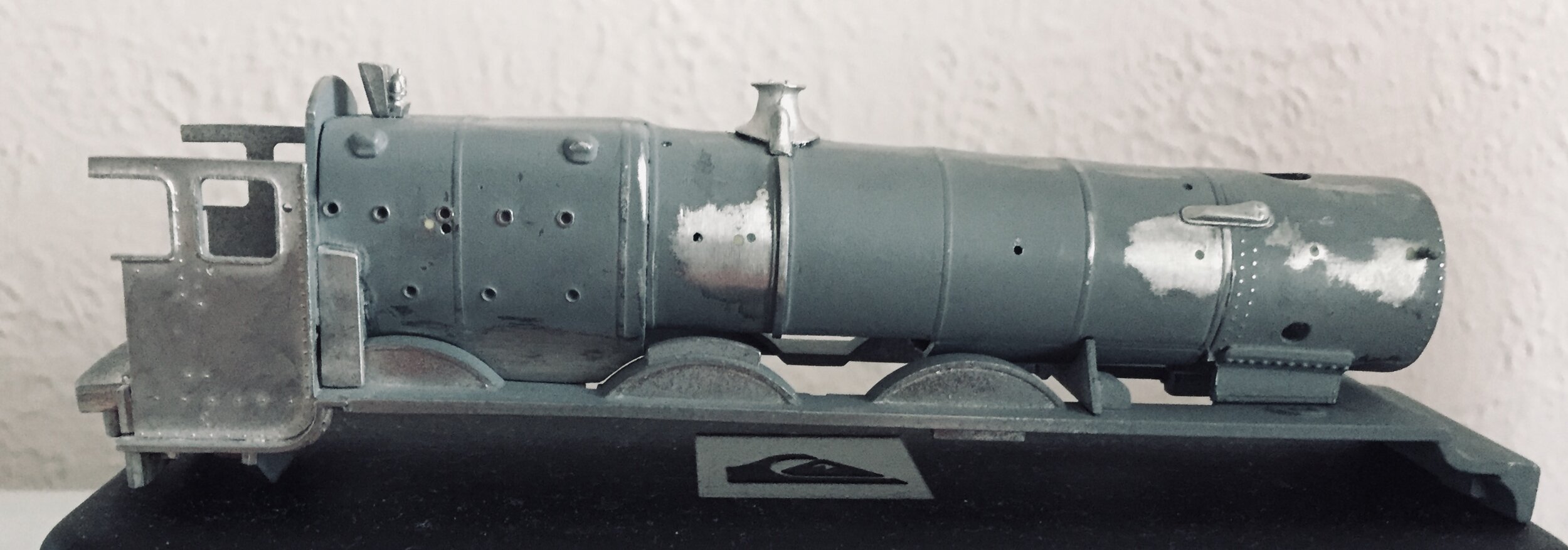
Work commenced on the boiler casting, filling joint lines and sanding them smooth [98% successful] and reshaping the front end. This, with filler and sanding, proved easier than anticipated although it was arduous and the supplied smokebox door will now not fit. I have a solution for that though. Offering-up the boiler to the repaired footplate showed that a lot of packing was needed in various places, too. Thin plastic card strip was used. The huge cut out in the boiler bottom [for the XO4 motor] was partially closed off with some scrap plastic although I had to leave a small opening to fit the new motor. Some moulded detail was also cut away and better quality mouldings fitted [eg. the two smokebox covers]. Finally, all of the handrail knob holes were filled and new, straighter ones drilled in the correct places. The photos below show where we are:
Things always look dreadful at this stage and until that final coat of primer is laid down, you wonder how it's going to end up. This one really is a horror though. You can clearly see the thick epoxy glue applied by the previous owner. Fortunately, only the boiler halves had been assembled and stuck onto the footplate, everything else awaited assembly. The whistles, their shroud and the safety valve cover are replacements from the bits box: the originals were unusable. The smokebox covers are replacements too: they are clearly visible in the left hand photo.
Now, an easy bit, the chassis. All pretty straightforward and it runs, too. Once a dry run with coupling rods and the cylinder cover / slide bar assembly has been undertaken, it'll be dismantled again for painting.
A very simple chassis arrangement, but it should be quite adequate for the task. Happily, the motor will not foul the cab and sits just behind the backhead.
You’ll see from the photo below that the body sits quite well on the chassis although some gaps remain to be addressed: it's far worse on the other side because I cut away the fire iron tunnel. Fitting the chassis into the body was difficult because of the width of the can motor. It just fits however. Clearances for the driving wheels appear to be OK and all are in line with their splashers [photo distortion suggests not]. Filling most of the gap in the lower boiler area has made a huge difference cosmetically also, the area left open [to allow he chassis to be removed for adjustment / electrical repair if necessary] being not really noticeable. The right hand photo shows the boiler before the gap was filled, the left, filled.
Additional and replacement parts: I have never managed to complete a loco kit without resorting to these and this one's no different. I have acquired several bags of nice bits originally produced to super detail the Triang Hornby Hall [think Albert Hall or Hagley Hall, or even Lord Westwood] from long-defunct M&L Premier Kits via eBay. These will be helpful. I have also taken parts from a scrap r-t-r Manor body to apply, particularly the ejector pipe and smokebox door: both will need adapting, but each is a 100% improvement. I do not plan constructing the white metal tender from the kit either but will replace it with a smaller and more attractive 3500 gallon tender, made from a pair of Bachmann and Mainline tenders and detailed with whitemetal fittings.
Finally, for now, I will not be using the white metal cylinder casings, slide rods or coupling rods either. The cylinders are overscale and rods, apart from being crude, are far too weak for sensible use. I have some etched nickel-silver rods to use in lieu and the cylinder casing/slide rod assembly is an adapted Hornby Grange one, not 100% prototypical but perfect for the job. I’ll also need to add a fillet of plastic card to the top of each side of the chassis block - you can see the cut out sloping away under the can of the Portescap (above), a profile designed for the XO4 to sit on. It badly needs levelling up.
Later…..
I spent an extremely frustrating evening test-running the chassis with the wheels and rods attached. The wheels are fine but, of course, with rods fitted, everything bound up and I bent a rod. I was able to straighten it out but a lot of careful reaming and the fitting of some tiny bushes was required before I obtained a free-running rolling chassis. I actually think that it will be OK now. The acid test be be refitting the motor and applying power of course: a high speed lock will spell disaster for the rods....
The front bogie has been built up and painted and it runs nicely too. I have to work on a method of fixing it to the chassis [it came from a different white metal source] and I might have clearance problems with the cylinder casings, but I just might be lucky too.
Photos below are the chassis block with the plastic fillets added to improve the profile [mentioned earlier] and an 'after' shot with the chassis painted and ready for a roll. The wheels, of course, will be painted in due course.


Next, I had planned to begin painting the footplate but disaster struck and it may very well spell the end of the build.
For a white-metal kit, this is just about as bad as it can get. The footplate is always the weakest part of the build and has no structural integrity whatsoever until it has been attached to the upper body and the chassis then attached. Everything is usually fine then but, until that time, the thinness of the footplate casting is vulnerable to handling and doesn't allow for much straightening following the inevitable bending caused by handling.
Having attached the cab steps, I was gluing in the injector pipes when the entire casting broke in, first, two places and then [after the photo], three.
I have reattached everything using superglue, epoxy cement and nickel-silver strip to reinforce the joints but whether this will last we'll have to see. I have set it aside for 24 hours anyway.

If it breaks again, there's really nothing which can be done. However, regardless of this problem, it is already clear that the model will be quite compromised in terms of dimensions and details: alongside a recent Hornby Hall it already towers and the cylinders are sited too far back from the buffer beam. The cab front is all wrong and the correct sized centre and forward drivers so close that I cannot fit brake hangers (annoying that). But that’s how things were 50+ years ago! More to follow…….
Well, another corner and another problem. The broken footplate casting is going to need gentle filling and sanding in due course and whilst waiting for the fix to cure, I started looking at the cab roof: attaching it would at least provide strength at the cab end of the footplate and stop that part from flexing.I decided to clean up the casting and glue it in place but whilst everything looked OK, I decided to check some clearances again before it was too late.
Just as well. The blanking plate stuck to the cab end of the firebox (to which the blackhead casting would eventually be attached) had been poorly positioned by the previous owner and resulted in the roof being essentially unfittable: it sat at a slope about 3mm too high. It was a thin, fragile casting too, attached by ladles of whatever had been used. It has to come away though as it is not just a simple matter of sanding it down. I think a new scalpel blade might be able to separate it, otherwise I’ll have to fabricate something out of plastic card. Today’s job.....
I had also planned to spray and line the boiler unit before attaching it to the footplate, it would certainly make lining easier. I’m not sure that it will be possible now. In spite of everything though, I am still enjoying this challenge…..
The fit of the roof has now been sorted. I was able to very gently prise away the backing plate, clean it up and reposition it properly. A tiny amount of filing will result in a good roof fit now. I have also taken a saw to the 4mm thick moulded fall plate, that will be replaced by something rather thinner and of the right shape in due course.
Unfortunately, the rather nice moulded sand boxes I have cannot be fitted: rather like the brake hangers, they would foul the drivers. I can fit some piping however to simulate the more visible part of them. I have also decided to hand-paint the boiler and cab for this one, rather than spray it. I am quite looking forward to that! Paint has been ordered [Railmatch very smelly enamel].
But all now hinges on the footplate repairs staying stable....
The repair to the broken footplate has held and it is strong enough to clean and handle once more. A lot of fiddling recently has sorted some of the fit problems but has not resulted in anything terribly photogenic. I am close to final priming and painting though and await fine weather. The top coat paint [post-1928 green] has arrived also and I've bought a new flat brush to use with it.
There are still a few difficult bits to resolve though, the worst of the potential horrors being matching the cross-head operated vacuum pump piston with the vacuum pump itself. The piston has to be able to slide in and out without catching and the fit is not going to be easy. The steam pipes are going to present problems too, but they are surmountable.
This thing does sit high though. Compared to a Hornby Hall, it towers. There is nothing which I can do about that, it's down to the sheer bulk of the castings. Look at the smoke box saddle for instance: I could file it down, but it would only result in an increase in the forward slope of the boiler. This is what you get with cheaper old white metal kits. You can see, too, that the cylinders sit too far back.

A solution to the height problem would have been to fit 22mm drivers instead of the correct 24mm ones. It would have helped greatly, but I only have four 22mm Romfords in my bits box and am not keen to spend a lot more on this model, particularly as the outcome is still unknown. I did consider shaving an mm or two from the top edge of the chassis block until I realised that it would cause all sorts of problems and shorts.
Anyway, here it is with its half-finished tender. Here, the Hall's height isn't so noticeable. The tender chassis need .5mm removed from its top however so that the bunker sits level. The Hall's front bogie is not attached but is simply place on the track.

I think that the upper-body assembly is pretty close to painting now. Some more fiddling with the fit has resulted in the smoke-box saddle sitting a little lower and I have also shaped a piece of thin plastic card to cover the large gap on the left-hand side of the fire-box created when I cut away the fire iron tunnel. Before and after photos below.


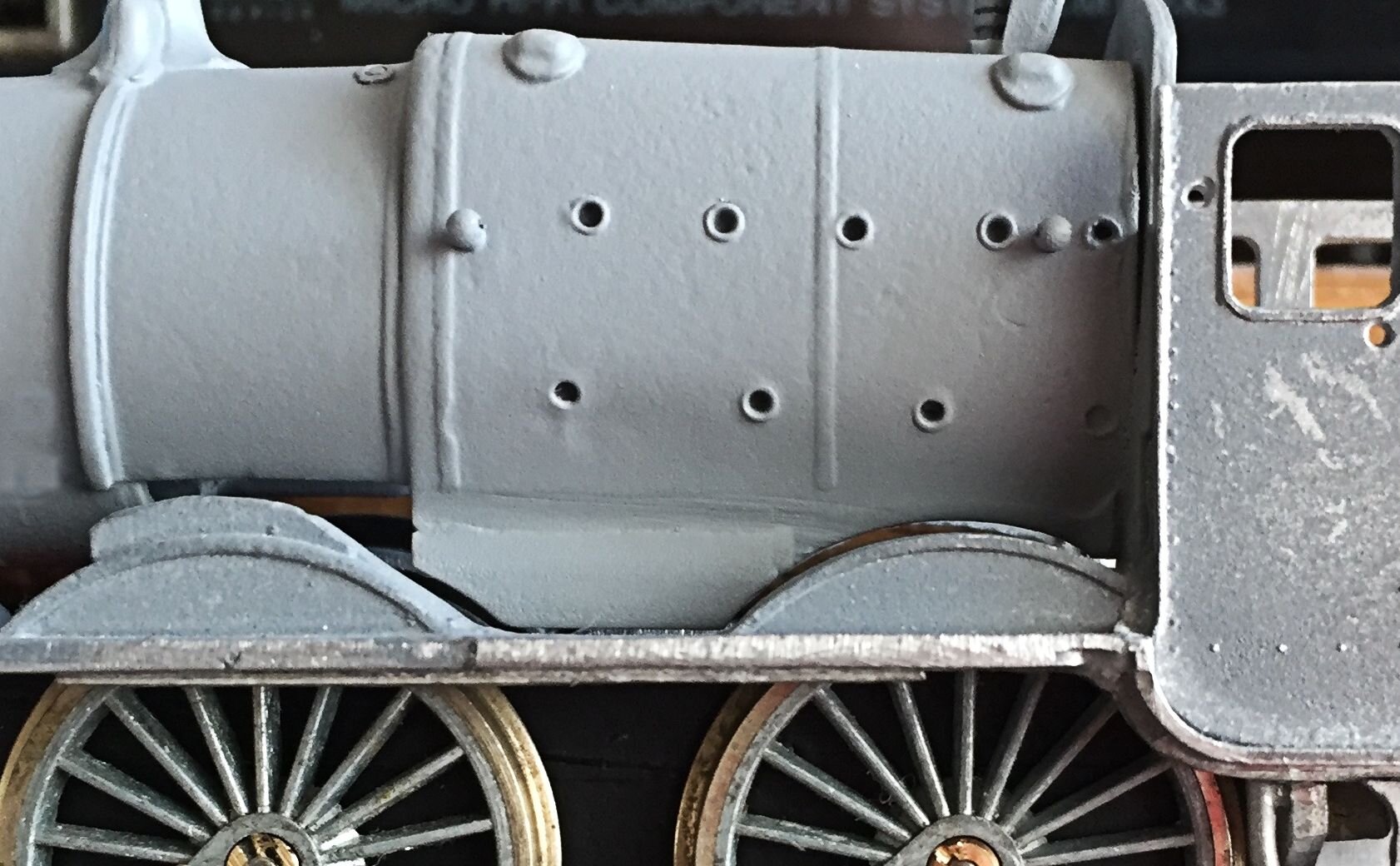

I have also had to spend time fettling the steam pipes which, believe it or not, were too short to fit. Unbelievable really. I found some plastic tubing which was close to the correct diameter and superglued it in place. Once set, an emery board tidied things up. The tubing will be cut to the correct length in due course. And that's pretty much the boiler unit done. Oh, I also found some nice cast washout plugs and fitted them into the top of the boiler, two by the firebox and two by the smoke box. One is just visible in the last of the cab photos above, just to the left of the fire-box.
It's a while since I posted an update on this frustrating build. Do excuse the quality of the photos - and the lighting - too, it was done on my phone at my desk.
First photo shows one of the [many] problems I've encountered whilst attempting to match parts from four different sources to produce a coherent whole. This is the area of the build that I was particularly concerned about, ensuring that the connecting rod from the slide bar to the coupling rod not only reached and ran a full rotation without binding, but also enabled the vacuum pump piston to travel in and out of the vacuum pump without sticking.

The problems here are obvious: bent footplate, slide bars not horizontal, vacuum pump piston at a ridiculous angle. But, on the positive side, the connecting rod reaches and rotates without binding. The rest is, with care, resolvable.
Second photo shows overall progress. The lining was fiddley but it sits reasonably well. I'm hoping that a light flash of eggshell varnish will both protect the lining and also make the five coats of paintwork look a little more uniform. We'll see.....

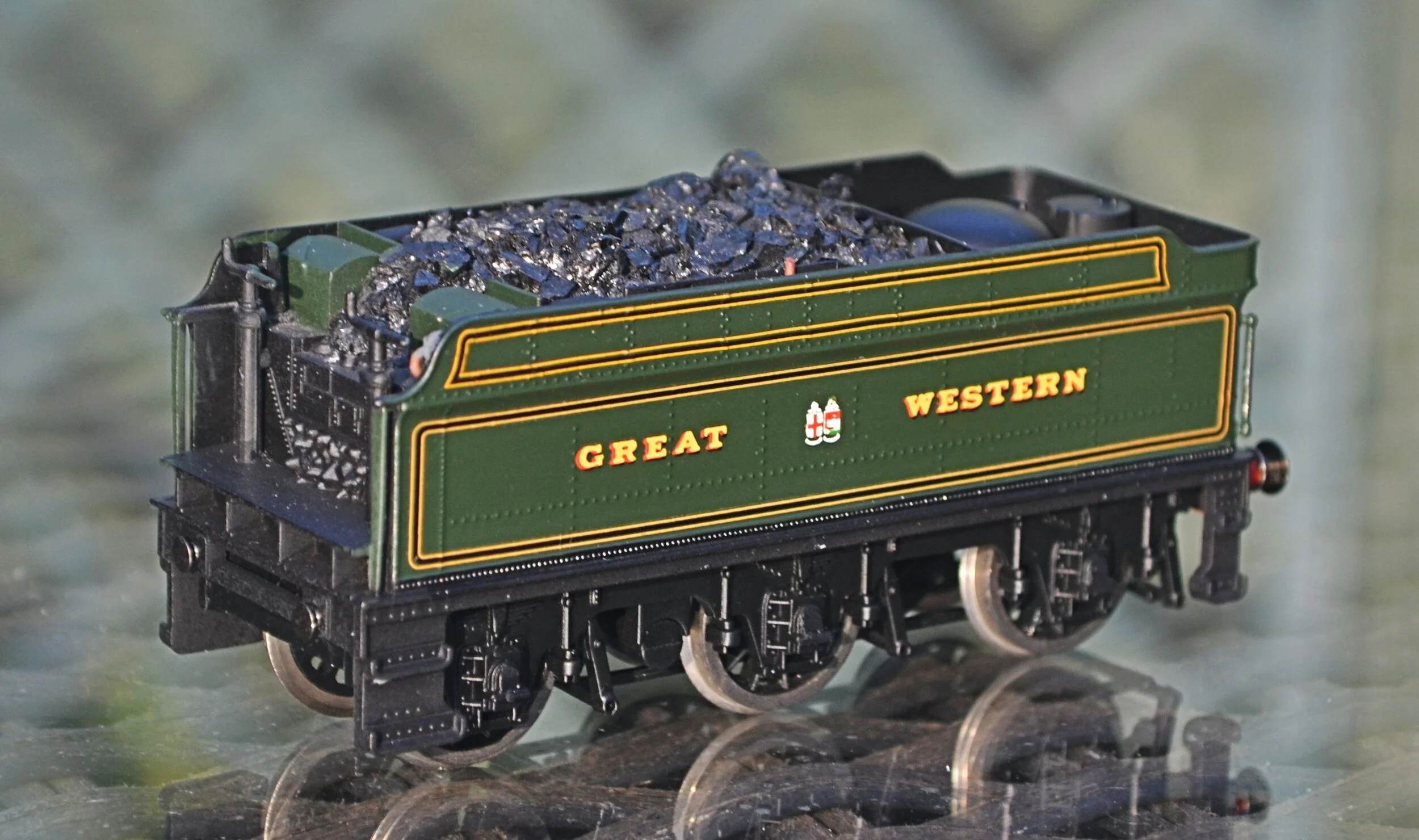
After a break away from this build, I returned to the puzzle once more. The tender is 95% complete now. It is an amalgam of three sources: parts of two r-t-r tenders and a bit of white metal and brass from the original and elsewhere.
There is still a little touching-up and painting to do.
The original tender was one of those ugly high-sided Hawksworth affairs and, being extremely heavy, would have created a lot of unnecessary drag. I wanted the smaller, prettier Collett tender and had some spare parts in the bits box which obliged well. The lining was easier than I had anticipated, too.
The loco body is by no means finished but we are well on the way now. The splashers need a further coat of green and I've knocked off a lamp iron somewhere along the way too. Buffers are sourced but yet to be fixed and the steam pipes [see above] are the next job, along with the roof and painting details inside the cab. Other bits of detail to be added in due course.

It is frustrating. Even the most careful handling results in damage and today, whilst attaching the bogie, I somehow managed to snap off a cylinder. Reattached with lashings of Gorilla Glue, it's back in place but will it be strong enough to handle the motion of the cross-head and piston rod? And talking of the bogies, they cannot be attached as the instructions direct once the chassis is attached to the body, and the chassis cannot be attached to the body with the bogies in place! I got around that though by reversing all of the fixings and attaching some plastic-card reinforcements from inside the chassis.
I have also lost all of the lamp irons! That's five that have now pinged off into the unknown. I really should have left them to the end though.
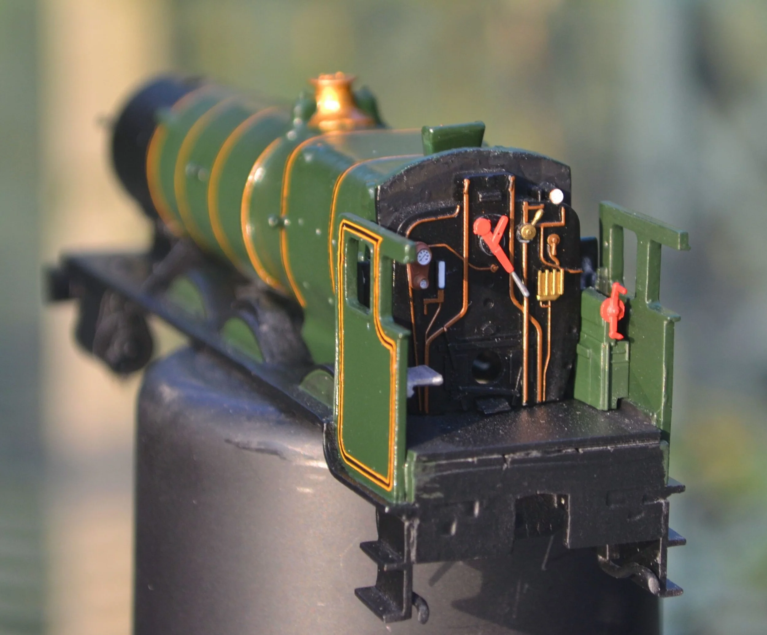
Anyway, in dazzling sunlight, here we are so far. I have attached the steam pipes, the boiler-side handrails, the roof, the reversing lever and the ejector pipework. The chimney is still a loose-fit. It is still nowhere near complete and a lot of detail parts need adding [and paintwork touch-ups carefully applied] but it is, at last, beginning to look like it should…..
As a footnote to the above photo, I've managed to assemble one side of the motion - the critical side really - and given it a dry run. Nothing is fixed permanently yet and it is running without power, but, happily, nothing locks up and everything appears sufficiently horizontal [unlike in the photo of the motion some way above].
It is a great relief that the vacuum pump piston moves freely, too. Of course, this is different from running at speed but it's an optimistic sign. Ridiculous really, attempting this using parts from three different and should-be incompatible sources!!!
Before continuing with the motion however, I decided to tidy up the buffer beam area, attach the buffers, vacuum pipe, coupling, reinstate the lamp iron that pinged off and fit their lamps. The spare lamps have been fitted in their correct position. I have also numbered the buffer beam and attached the name plates above the central splashers on each side.
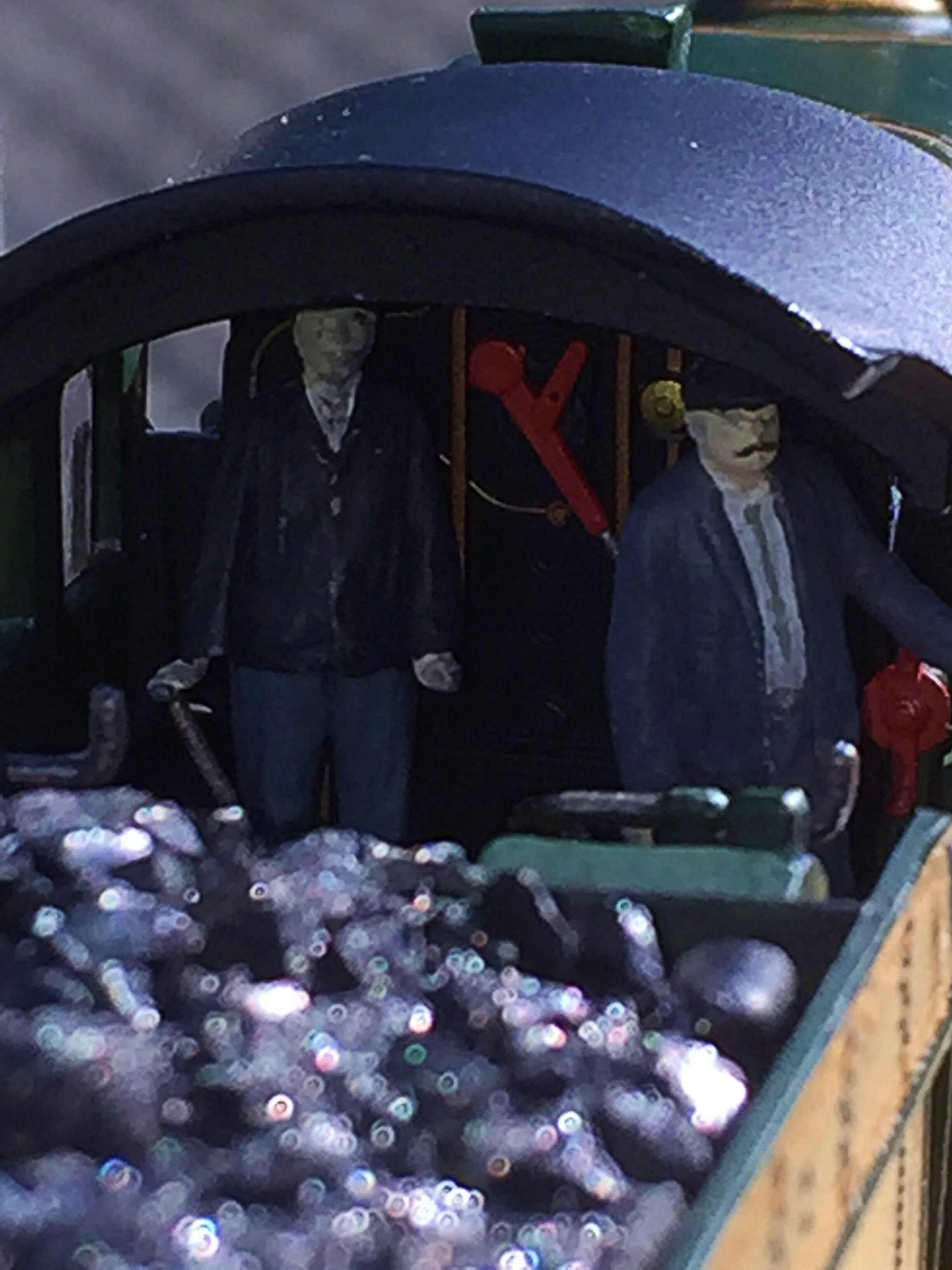
At the other end, the crew have also been painted and installed.
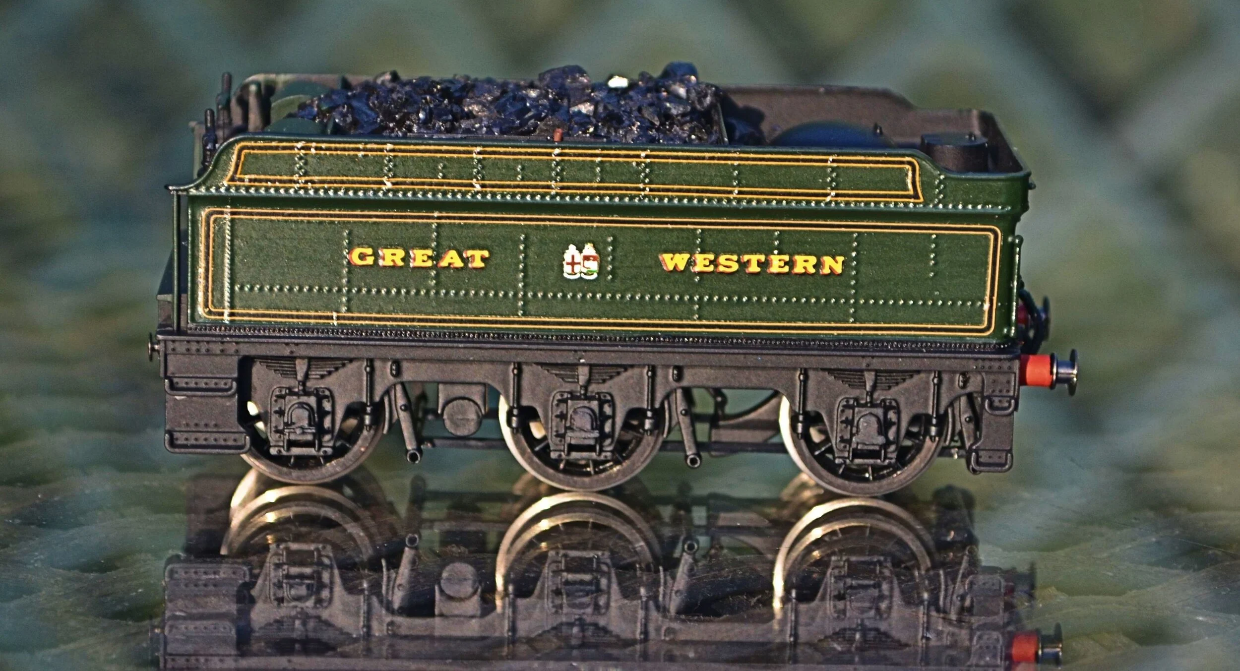
The right-hand side of the tender has also been re-lettered as the original ‘GREAT WESTERN’ was about 2mm too high and it really began to annoy me! It looks far better now and was achieved without causing any significant damage to the paintwork.

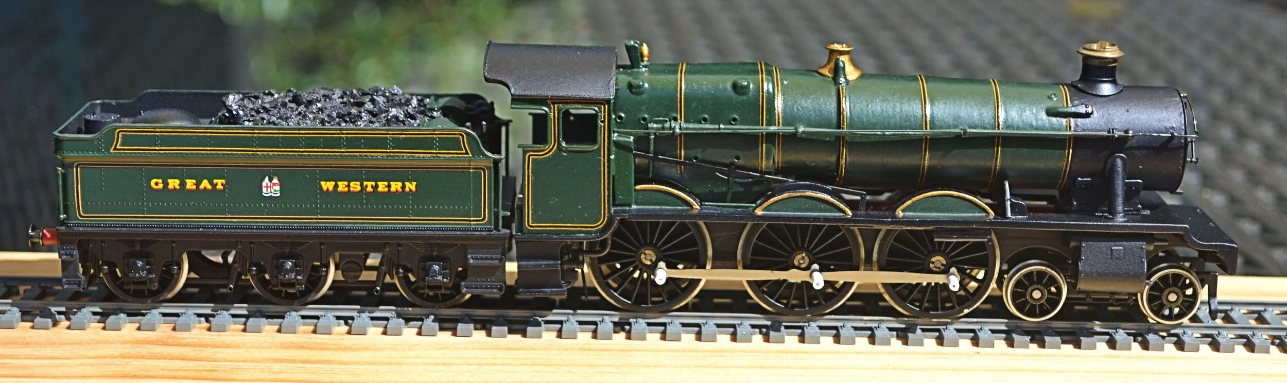
This is probably the final posting now for this build. It is, at last, finished. All of the pretty embellishments have been added and the boiler has been given a light polish to bring out the colour. A draw-bar has been fabricated to couple the tender to the loco [which swivels at both ends], the copper and brass pipework has been varnished and the front bogie attached. Various bits which got knocked off along the way have been reattached, too.
On the rolling road the loco ran smoothly without rocking or stalling: a relief as I had spent five hours trying to eliminate some binding in the motion which may have been down to some problem with the right-hand slide bar.
When the motion binds, the variables may be huge and sometimes a solution is found without even knowing how it happened: the slide bars have to be at the correct angle through all planes, they also have to be parallel. The connecting rod, where it joins the coupling rod, has to be at the correct angle and not bind against the nut. The cylinder and vacuum pump pistons must not catch. The soldered caps on the front axle mustn't catch the connecting rod. The list goes on.....
Regrets? Only in so far as it wasn't possible to fit brake gear to the loco, which isn't too bad, really. I think, before entering it in the club's competition, I'll polish the boiler again to bring out the colour a little more.


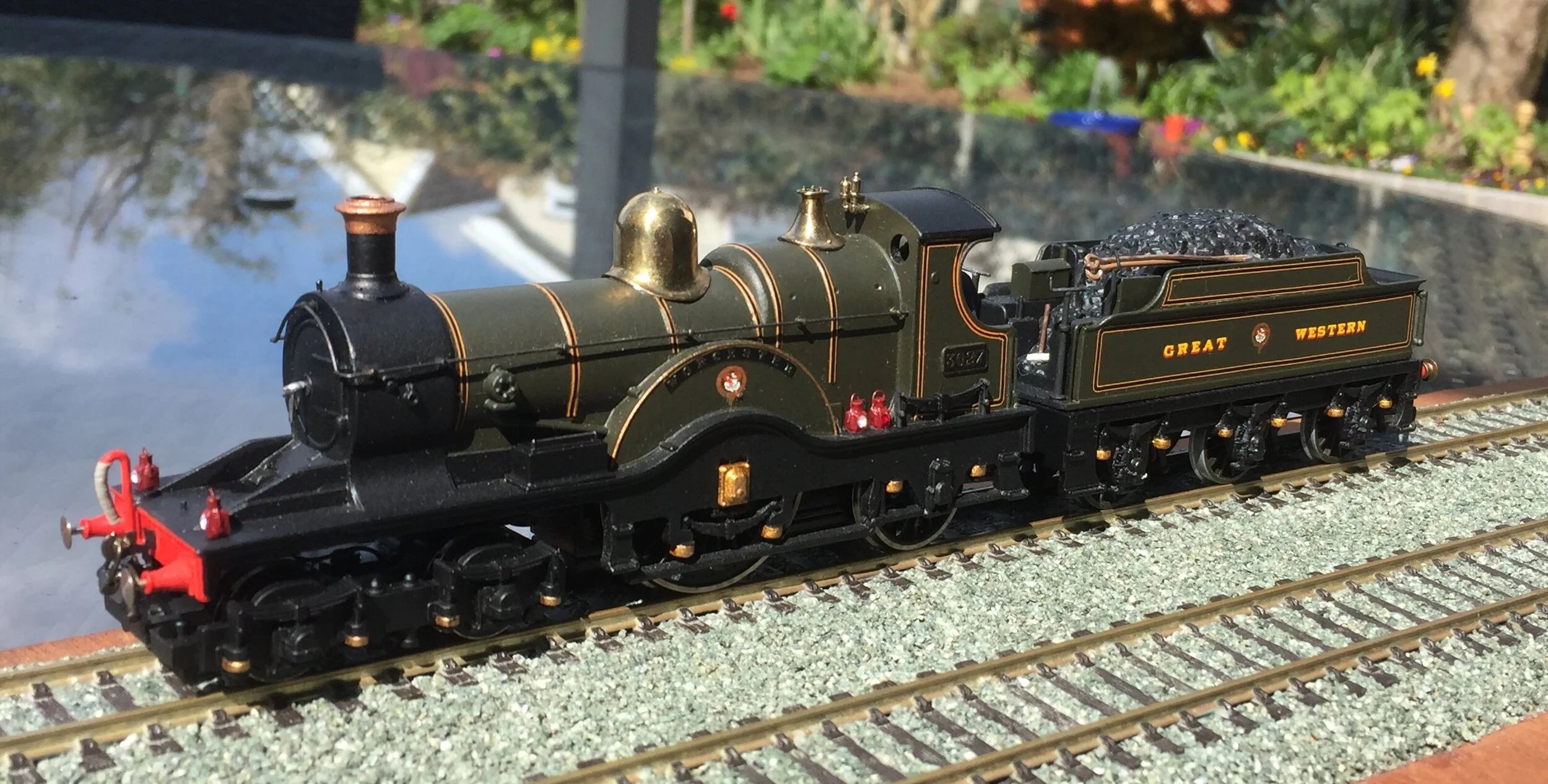
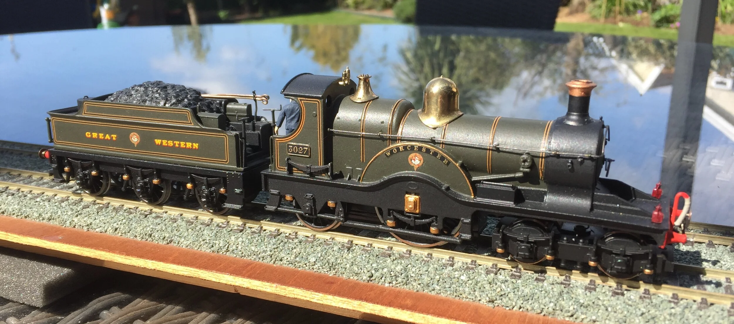
This next build [well, conversion] was undertaken around 15 years ago but, unfortunately, I did not record it as it progressed. Nevertheless, it is an interesting engine and worth commenting upon here.
It is, of course, a model of the Great Western Railway’s ‘Achilles’ Class 4-2-2, otherwise known as the ‘Dean Single’. These vintage greyhounds were top flight express locomotives in the late Victorian / early Edwardian period, with the first eight members of the class being rebuilt conversions of earlier Broad Gauge locomotives. A total of 80 were built but as ‘singles’ they soon became outdated and withdrawals began in 1908. The last member of this stylish, handsome class was taken out of service in 1916.

The ‘Single’ is best known by most modellers from the Triang model, ‘The Lord of the Isles’, first introduced in 1961in a train set with their generic GWR clerestory coaches. Also available on its own [and for a while with smoke, too], it appeared sporadically until 1981 when Hornby reissued it in a train pack for two years. From time-to-time thereafter, Hornby offered it alone, or in a train pack, under different names [eg. ‘Lorna Doone’, ‘The Flying Dutchman’ and ‘The Duke of Edinburgh’]. Hornby also sold it in their ‘Thomas’ range as ‘Emily’. The later Hornby issues had a completely unaltered Triang body although their newer chassis was a considerable improvement. It is not currently available. Some may also remember it being issued in near-N gauge by Matchbox [Lesney], as ‘The Duke of Connaught’, between 1959 and 1963. The ‘Duke’ has no tender however! The photo above shows an early Triang ‘Lord’ in fairly typical condition. It probably dates from the early ‘60s. The donor model for this conversion was in an appreciably worse state!
The conversion undertaken for ‘Worcester’ involved removing nearly all of the moulded detail from the original Triang body, including the hand-rails, whistles, safety valve bonnet, steam dome and chimney, opening out some of the solid webbing above the springs for the driving wheel, replacing the buffers with correct Dean-pattern examples and paring away the moulded handrails. The tender had its plastic wheels replaced with metal ones, running in brass bearings and brake gear fabricated for it as well. The tender chassis was retained but the body was substituted by a detailed one from an Airfix Dean Goods. A great many lost-wax brass castings and white-metal mouldings went into the rebuild and the loco and tender were hand-painted in GWR pre-1928 green and lined using Pressfix GWR loco lining. Etched brass name and number plates were fitted to the loco and the backhead was detailed prior to fitting crew. For some years this conversion ran with its original Triang mechanism, this was eventually replaced by a Hornby version however, an improved chassis [with pick-ups on the front bogie as well] taken from a ‘Thomas’-range ‘Emily’ when they were, briefly, quite cheap. The photographs of the finished model, below, remind me that I must fit some brass spectacle frames, too.