The story of the Great Western Railway’s first, last and only Pacific, No 111‘The Great Bear’, is well-enough known. Built to great fanfare as the UK’s first Pacific in 1908, it was withdrawn to be rebuilt as a Castle, ‘Viscount Churchill’, in 1924, having been superseded both in technical terms and power by the magnificent Castle 4-6-0s, a class which, with the later Kings, remained pre-eminent in GWR passenger express terms until their demise well after Nationalisation.
However, in 1941, within the Drawing Office of the Great Western Railway in Swindon, some thoughts were given to the design of a new Pacific locomotive to meet post-War demand, a class which has been unofficially given the name of ‘The Cathedrals’ and numbered from 8000 forward. The actual history of this project is a little difficult to unravel as some accounts give the origin to FW Hawksworth whilst others state that he was instrumental in cancelling the project as soon as he heard of it. Whatever the case, the project did not proceed and no ‘Cathedral’ was ever built.
This ‘might have been’ has always enjoyed a fabled life within Great Western history however and, occasionally, someone builds a model of one. One or two can be found online by simply ‘googling’ around for them, but they are precious few and far between. Consequently, embarking on such a project requires some determination as, when I commenced, I found some photos of one fine model, two artists’ illustrations from some books and a line drawing. That was it! And, largely, for that reason, this project remained a pipedream for some years, until I found the image below……..
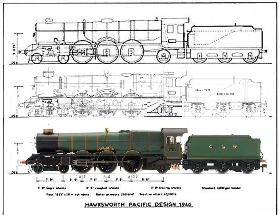
This image, together with some online comments and the account of an earlier model build a 2008 The Railway Modeller, showed that it would be possible to construct a ‘Cathedral’ through a complicated shut-and-shut, utilising China-made Hornby LMS Princess and BR King locomotives, together with a Hornby County tender unit. An expensive project certainly, but a worthwhile one and, having acquired the parts required, I set about building No 8000 ‘Gloucester Castle’.
The starting point, two dusty but otherwise fully working models……

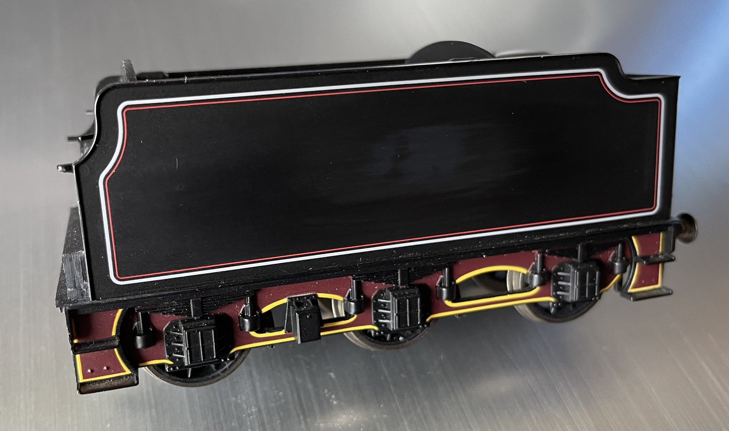
I decided to commence with the tender. The Hawksworth body has had all of the parts below the slight ledge at the bottom removed and the Princess chassis has had surgery to the top side to enable the body to sit flush. All of the moulded handrails, steps, etc., have been cut away, to be replaced by wire and etchings in due course. I retained the Stanier tender chassis as it was wired for pickups and will couple naturally to the modified Princess chassis. Not surprisingly, the side steps look a little too Stanier for my liking though and they will be altered later, they just need the curve removed really. Whilst some internal surgery to the Stanier unit was required, the photograph shows a comfortable dry fit between the two parts, and a successful start!
Now, turning the the Princess’ body, the handrails and the chimney have been removed, a very long run of moulded pipework has been cut away from the left-hand side, the cab roughly removed and the safety valve 'blister' above the firebox sanded back. The pipework was a bit of a nail-biter as I couldn't risk damaging the boiler side. A wide bladed craft chisel made light work of it however and no gouges occurred. I spray primer regularly to check the profiles of what has been removed to ensure that all is flush. Most of the running plate along both sides will also have almost all of its moulded detail removed. I have made a start on that.
The topfeed will soon need removing also, to be replaced by a traditional GWR brass bonnet and the holes for the original safety valve castings filled. I'm currently mulling how to construct a fire-iron tunnel for the left side of the body....

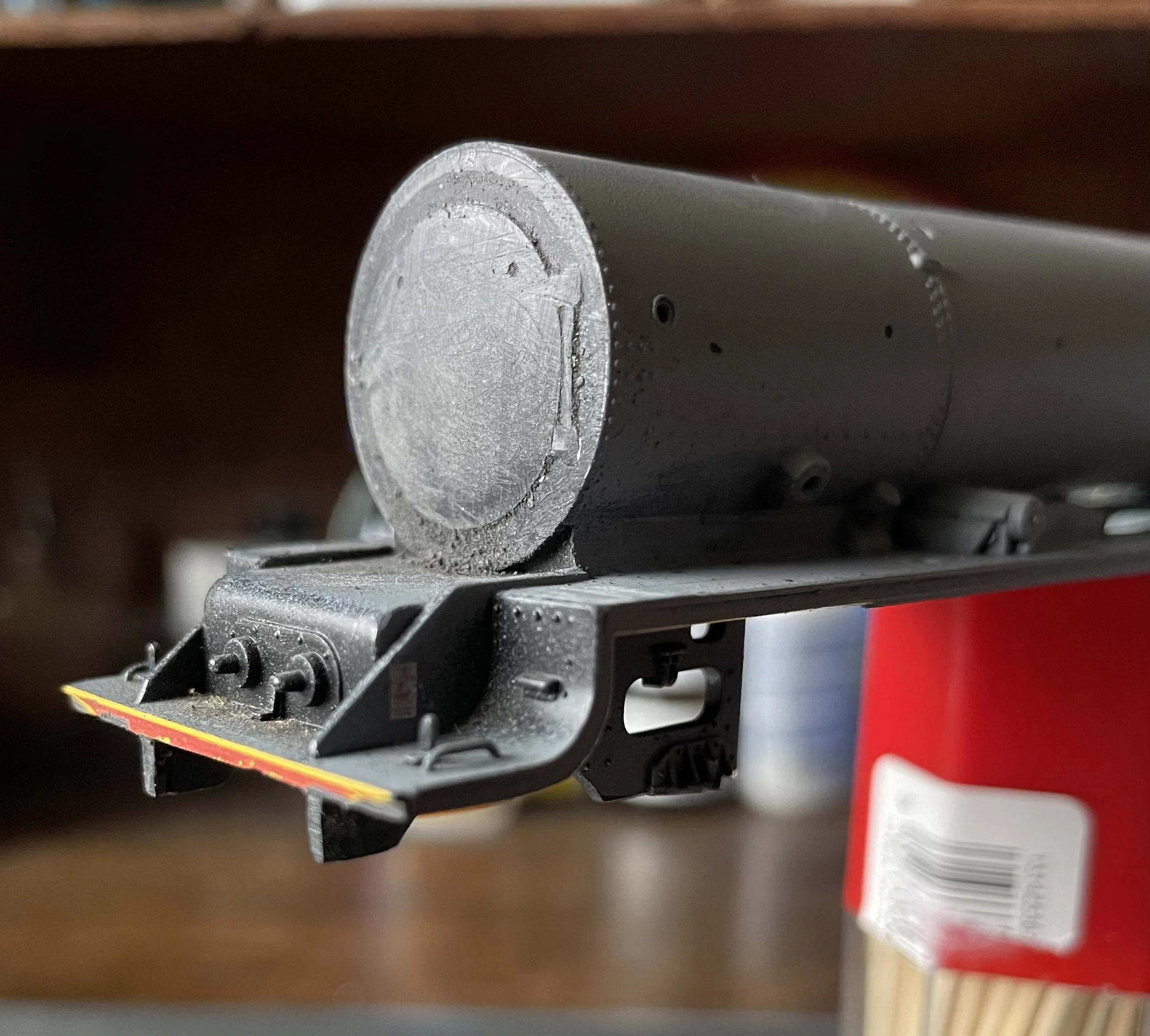
The next photographs show continuing work on the Princess. The smokebox door was sanded back with increasingly finer grades of paper until the face was perfectly smooth. It couldn’t be removed any other way as it was integrally part of the thick front moulding and not a separate item. That task took a long time and was not totally finished by the time the photograph was taken.
The Princess’ buffer beam was also carefully cut away to allow the King’s to be fitted later. The topfeed has also been taken away and the boiler top made good.
The King’s body has had the cab cut away and then sanded back carefully to its front face to provide a smooth surface to mate with the Princess fire box. The rest of the cutaways were rather more ruthless and the smokebox front, the buffer beam and the chimney were hacked out of the thick plastic moulding to be cleaned up later. The King’s steam pipes have also been removed and set aside for use later.

The King’s body was of no further use now. Sadly, the reversing lever and the handrails were too short for reuse and they, and the remains of the body, were stored away for possible further use on another project.
The next two photographs show the cab and various other parts scavenged from the King’s body for reuse. The two white-metal items are a replacement safety valve bonnet and a more realistic screw reverser. The item which looks like a robotic dog tick is the mechanical lubricator. The cab front looks quite rough but in fact there was no damage to it at all. The underside of the double chimney was difficult to reprofile to match the radius of the Princess’ smokebox, but this was eventually achieved by wrapping a broad pencil in sandpaper and using it as a radiused file to obtain a good fit.
With all of the parts now ready for assembly, it was time to work out how to invisibly attach the King’s cab to the Princess’ firebox. Neither were exactly the correct shape or the width to make this an easy task and the King also had the side casing for the reversing lever mechanism to be accommodated. A lot of sanding and filling made this eventually possible and the unit was set aside for the glue and filler to cure and await further sanding while attention was given to the two chassis for the first time.
The Princess bogie was removed and stored away. The trailing truck was removed also and all of the wring disconnected to save damage during handling. The first major change involved swopping the Princess’ driving wheels for those from the King and to do this, the wire to the pick-ups attached to the keeper plate needed to be cut to enable full access to the underside of the chassis. This cut took place on top of the chassis, as resoldering there would be far easier than on the keeper plate, with the risk of heat damage to the plastic. The nuts securing the Princess’ wheels to their connecting and piston rods were undone and the wheels removed. The wheels from the King were inserted in their place and the Princess’ connecting rods re-attached to them. The rods from the King could not be used as they were too short for the Princess’ wheelbase. With the wheels exchanged, the keeper plate was reinstalled and the pick-up wire threaded back through the chassis to the top. Soldering awaited later.
The cylinder mouldings, piston rods and the entire slide-bar assembly were next removed from the Princess. The equivalent units from the King were removed also, its cylinder assembly separated into two parts and through continuous trail and error, each part was inserted under a partially unscrewed ballast weight on the front top of the Princess’ chassis. To achieve the correct fit, one which allowed the King’s piston rods to be assembled and the cross head slide back and fore without catching on the nuts securing the front driving wheels, a number of dry runs were required and a deal of metal had to be filed from the chassis block itself. There is absolutely no easy way of achieving this and patience was required but, after an awful lot of fettling with the sitting of the cylinders and the position of the slide bars, a satisfactory motion was realised and with power applied directly to the motor, everything ran nicely without binding. Screwing the ballast weight back in place kept everything square and tight. There was a bit of resoldering to do before I could try the chassis on the track though.
The photo below shows the body with its new cab sitting loosely on the adapted chassis. Not withstanding the slight fish-eye effect of the phone camera lens, it shows a number of things: the running plate has been cleared of most of its fittings and now requires some cosmetic repairs, the trailing truck is sitting too far forward, the cab has developed a slight rearwards lean and the frames beneath the firebox need to be extended towards the cab steps to close up the daylight. This was never going to be an easy build and the aspect of the cab has become a significant worry. The splashers will all require attention, too.
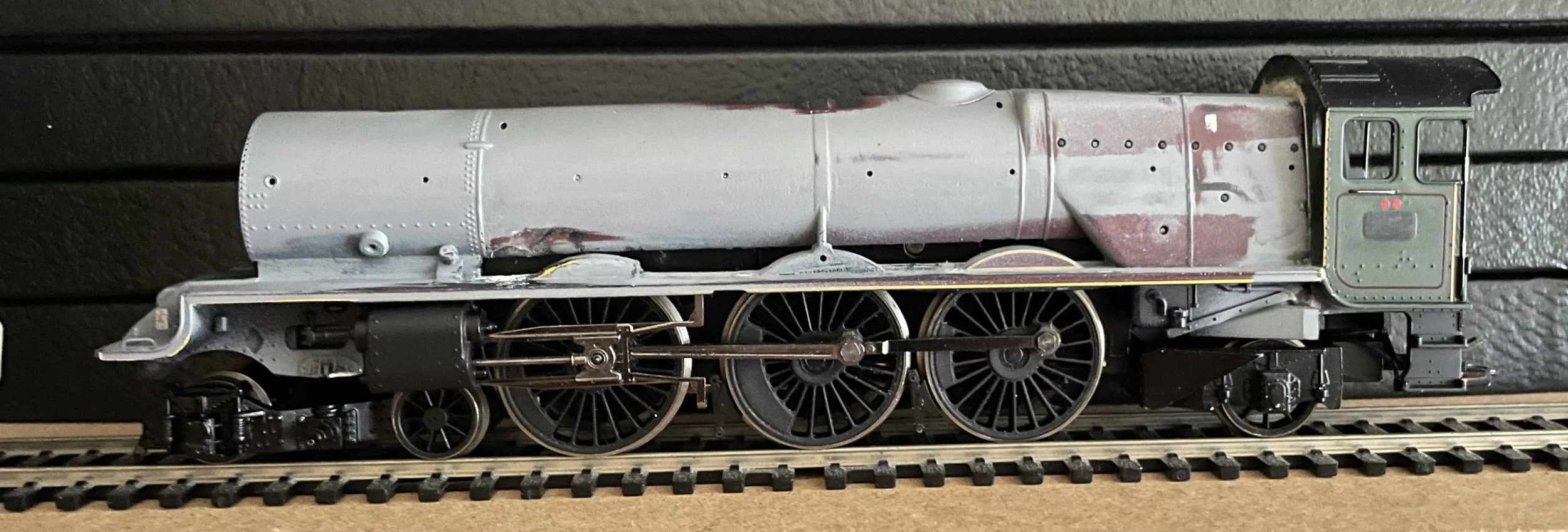
If you wish to attempt this build, remember that the connecting rods are from the Princess and the piston rods are from the King. The wheels are from the King also.

Some very nice etched plates for Gloucester Cathedral (8000) have arrived. I needed now to source a turned brass smoke box dart as the fragile original did not survive removal.
Before dealing with the problems of the body, the King’s bogie required attaching to the chassis. To do this, the original fixing peg was sawn off and a hole drilled in its place to enable a screw fit into the hole left by the Princess’ bogie. The bogie sits just a little too close to the front driver really, but it was optically essential that the front wheel of the bogie sat directly under the cut-out in the chassis. As it is, nothing touches or catches, so it’ll stay put.
The rear truck required lengthening by 3mm and to achieve that, it was cut in half and lengthened by soldering a brass strip between the two halves. As an idea it was faultless [!], it reality, whilst the

front of the bogie took solder well, the large cast end was too much of a heat sink and I had to screw the strip in place. See the photograph for an explanation. Painted black it’ll not show and the gap underneath with filled with plastic card cut to size.
All of the broken wiring was now resoldered and the assembled bogie given a good run on the Club’s test track. Some very slight readjustment to the siting of the cylinder and slide bars was necessary but, after that, the chassis ran smoothly and could be put to one side for the bodywork to proceed.
First, the frames have been extended back under the cab and, once painted, the cosmetic difference will be huge. I have also fitted the under-cab plumbing. I may - may - have a problem with clearance for the truck to swing under the cab though as there is precious little room for this . I'll test it at the club in a couple of days. The photograph below shows this, and also the smoke-box door, front buffer beam, double chimney and safety-valve bonnet have now been fitted in place. This is at last beginning to look like a Great Western loco! The problem of the cab’s aspect remains however….

And finally, for now, the first opportunity I've had to put everything together to check where we are cosmetically after fabricating a fire iron tunnel. Ignore lens distortions once again. I'm pretty pleased on the whole, but there is just so much left to do. Next job, assuming all runs well, will involve fabrication fronts and tops for the splashers, adding fixing points to the underside of the running plate for the slide bars and beginning to plan how the complicated piping that runs the length of the right hand boiler side can be fabricated. It is also clear that the tender is a tiny bit too low, that will be remedied easily. It’s issues at every step of the way with this one, and you can see more clearly now the problem with this side of the cab…..

So, more surgery required. Staring with the tender, I raised the body by 1.5mm by glueing some micro rod around the top of the chassis. I also used this opportunity to cut away the Stanieresque steps and attaching in their place the steps from the Hawksworth tender. A big improvement once painted. The tender now sits at the right height.
Next, I had to deal with the cab. This was a real problem as its complete removal would have caused a great deal of damage, it having been attached so robustly, particulalrly to the lower chassis. The only solution was to careful cut down between the cab front and the fire box to the running plate, avoiding the casing for the reversing lever mechanism on the right hand side, and then inject superglue in from behind, pressing the two halves together until it cured. This was an act of desperation really and I very much doubted that it would work. If it didn’t, I had no plan ‘B’. Using a fretsaw with a very fine blade, the cut was made without damaging the cab front. Superglue was applied from inside and the cab pressed against the firebox for ten minutes. It actually worked. White Milliput filler was used externally to fill out the saw cut and sanded back when cured. The result was a near-invisible join and no signs of stress in the mouldings. Back on track!
The next photograph shows more work on the body. The cab's angle-of-sit is now very much better. The splashers have been addressed on both sides, the front completely rebuilt and the rear sheeted over on the tops. I have fitted a speedometer and also begun to build up the complicated run of piping on the right hand boiler side. Theses last two issues are not shown below however. Again not shown yet, most of the holes for the boiler handrail have been filled and new ones drilled. The chimney has been re-seated more effectively also and the mechanical lubricator attached. The angled steam pipes from the King have also been adapted and fitted in place. Regular sprays of primer highlight defects quite helpfully.

The tender improvements are now complete and the body awaits priming and painting / lining, after which coal will be added. All of the moulded details were carefully pared away and were replaced by brass items.

And below is probably the final photograph of the Cathedral's body before a final coat of primer prior to painting. I have now fitted the long run of plumbing along the right hand side of the boiler. It is 100% speculation as no illustration exists to show what it would have looked like and, consequently, modelling after the King seemed the only option. I used various runs of plastic and white metal rod together with some parts from the King to simulate what might have been there. It looks rough now, of course, but paint will deal with that. After priming, I'll need to drill six or seven small holes through the piping to accept handrail knobs as the handrail lies directly over it. Drilling shouldn't be a problem, doing it in an absolutely straight line maybe however!
And I've just remembered that I have still to fit the smokebox door dart and some lamp holders on the front of the lefthand running plate - two minute jobs.

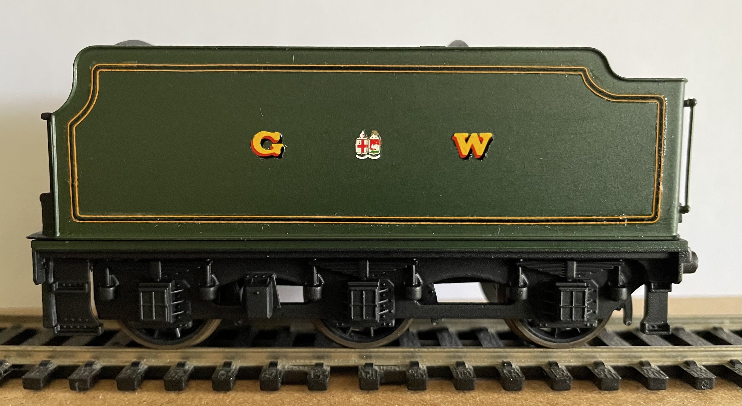
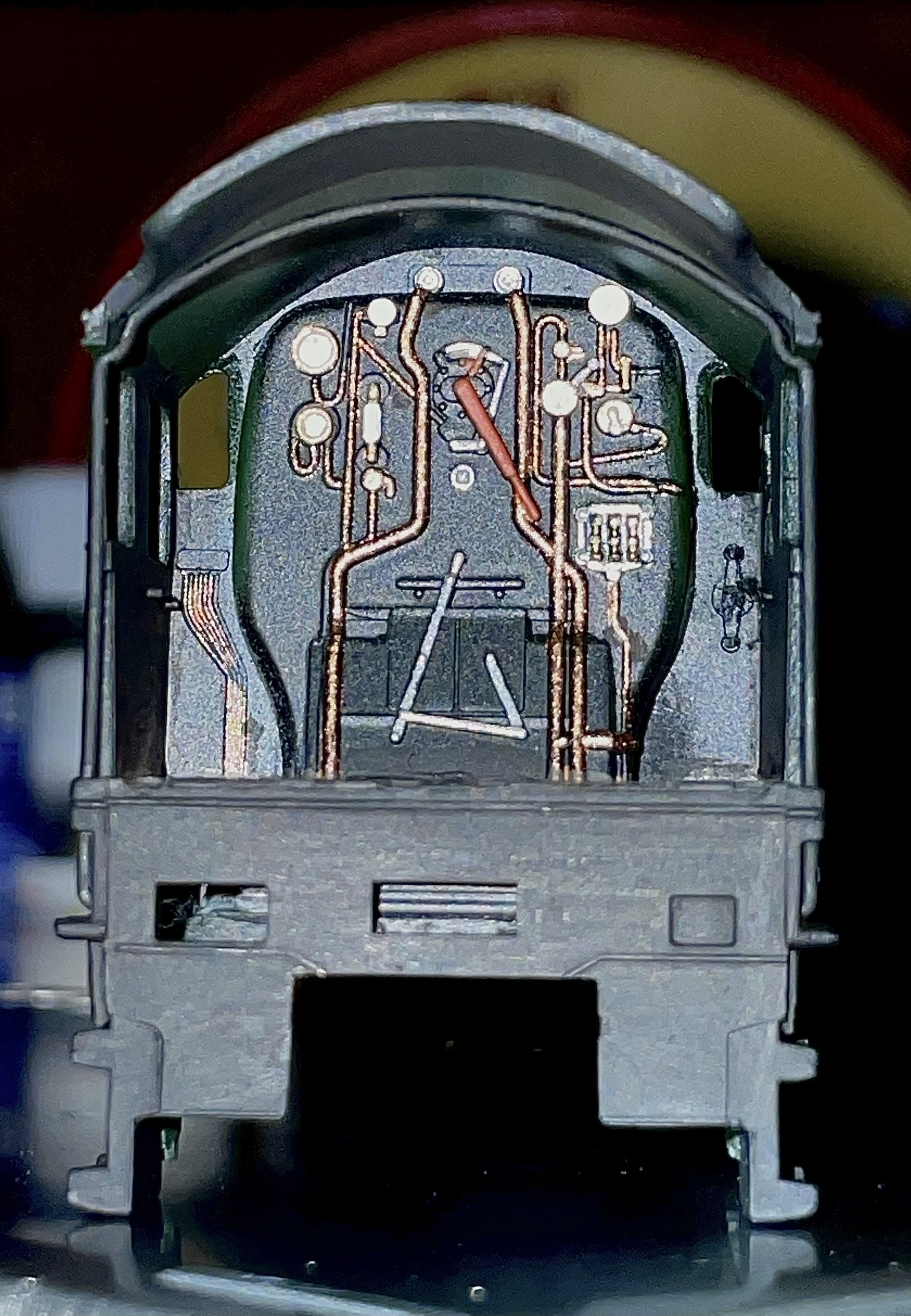
The next two photographs show the tender having been painted, lined and lettered [it awaits buffers and couplings], and the cab back-head detail picked out [the screw reverser has been painted but not yet fitted].
The loco body was now ready for painting also. A number of final detail fittings will be applied after and these include cab glazing, the reversing lever, name and number plates, whistles, buffers, hand rails, vacuum pipe and dummy couplings. The next photo shows the body painted and partially lined.

And below, with the lining completed, detail parts added and the chimney and bonnet painted and the whole varnished. I’m very happy with the finish. The handrails now await completion and painting.
The reversing lever was the final major job. It was constructed out of laminates of 1mm phosphor-bronze pick-up strip, pieces of plastic card and some brass etch. It contains nine parts.


And now, all of the finished parts united for the first time. The tender’s running height and the re-positioning of the cab justified the remedial work undertaken. Several hours a night over two months have achieved what was originally intended in spite of doubts arising every other day and a number of false starts!
This was not a cheap project by any means, so failure couldn’t really be considered. It wasn’t intrinsically difficult either however, although it was certainly fiddley at times. That said, it would be within the scope of any competent modeller who had the tools and the time, ‘the time’ probably being the single most important factor as real and repeated patience was required in bucket-loads.
And finally, is it accurate? No-one can really say. The locomotive was never built and of those illustrations that exist, most are artist’s impressions. This model is as close as I could get to the coloured picture at the top of this article and that’s good enough for me!

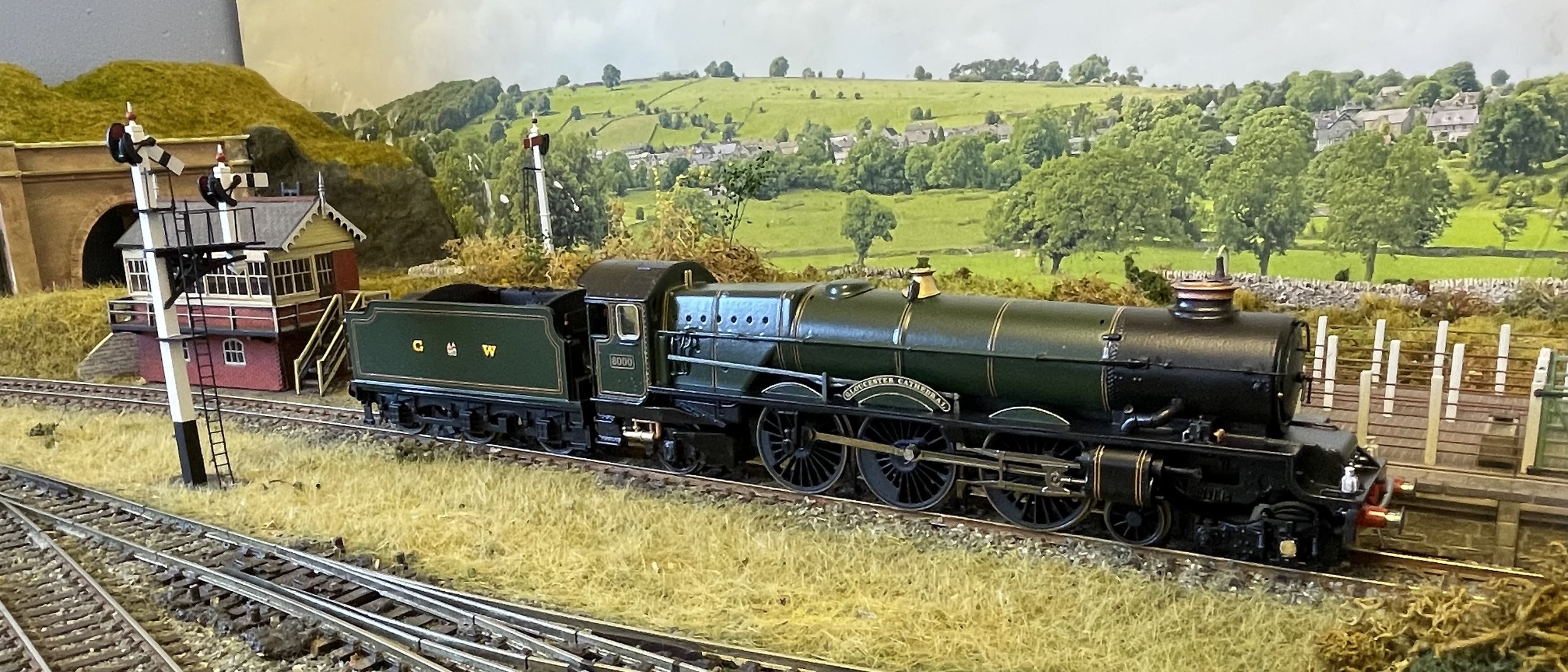


A final photo with the double red route indicator disks applied below the cab window.


